Cisco 891W Hardware Installation Guide - Page 93
Verifying Connections
 |
View all Cisco 891W manuals
Add to My Manuals
Save this manual to your list of manuals |
Page 93 highlights
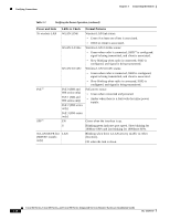
Chapter 3 Connecting the Router Verifying Connections Verifying Connections To verify that all devices are properly connected to the router, first turn on all the connected devices, then check the LEDs. To verify router operation, refer to Table 3-3. For full LED description, see Table 1-4 and Table 1-2. Table 3-3 Verifying the Router Operation Power and Link LEDs to Check Normal Patterns Power OK On when power is supplied to the router. To servers, PCs, workstations, or an external Ethernet switch connected to the LAN ports (FE01, FE1, FE2, or FE3) LAN 0, LAN 1, LAN 2, or LAN 3 On when the FE LAN port is physically connected to a server, PC, workstation, or external Ethernet switch. To FE WAN line WAN FE4 On when the WAN Ethernet carrier has detected status. To xDSL2 line xDSL CD Blinks when receiving or transmitting data. Green when the line is connected to the xDSL DSLAM3. xDSL Data Green when receiving or sending data. To ISDN line Data BRI LNK Green when the ISDN line is connected. Data BRI B1 and Green when the channel is connected. B2 3G4 WWAN5 Green when service is established. RSSI6 Slow blinking when searching for service. Amber when service is not established. Green when signal strength is high. Off or slow blinking when signal strength is low. To PPP9 clients To VPN12 tunnel CDMA7 GSM8 PPP VPN Fast blinking when signal strength is medium. Green when service is established. Green when service is established. Green when either a PPPoE10 or PPPoA11 client is running. Green when a crypto session is running. Cisco 860 Series, Cisco 880 Series, and Cisco 890 Series Integrated Services Routers Hardware Installation Guide OL-16193-07 3-37
-
 1
1 -
2
-
3
-
4
-
5
-
6
-
7
-
8
-
9
-
10
-
11
-
12
-
13
-
14
-
15
-
16
-
17
-
18
-
19
-
20
-
21
-
22
-
23
-
24
-
25
-
26
-
27
-
28
-
29
-
30
-
31
-
32
-
33
-
34
-
35
-
36
-
37
-
38
-
39
-
40
-
41
-
42
-
43
-
44
-
45
-
46
-
47
-
48
-
49
-
50
-
51
-
52
-
53
-
54
-
55
-
56
-
57
-
58
-
59
-
60
-
61
-
62
-
63
-
64
-
65
-
66
-
67
-
68
-
69
-
70
-
71
-
72
-
73
-
74
-
75
-
76
-
77
-
78
-
79
-
80
-
81
-
82
-
83
-
84
-
85
-
86
-
87
-
 88
88 -
 89
89 -
 90
90 -
 91
91 -
 92
92 -
 93
93 -
 94
94 -
 95
95 -
 96
96 -
 97
97 -
 98
98 -
99
-
100
-
101
-
102
-
103
-
104
-
105
-
106
-
107
-
108
-
109
-
110
-
111
-
112
 |
 |
