Cisco 891W Hardware Installation Guide - Page 82
Connecting the AC Adapter
 |
View all Cisco 891W manuals
Add to My Manuals
Save this manual to your list of manuals |
Page 82 highlights
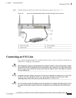
Connecting the AC Adapter Figure 3-24 Connecting PoE Chapter 3 Connecting the Router 1 4 5 3 2 2 4 6 231995 1 48-VDC PoE input jack 2 Power cord 3 Power adapter-48 VDC Connecting the AC Adapter 4 AC plug 5 12-VDC input power-jack plug 6 Power adapter-12 VDC Warning The device is designed to work with TN power systems. Statement 19 Warning This product relies on the building's installation for short-circuit (overcurrent) protection. Ensure that a fuse or circuit breaker no larger than 120VAC, 20A U.S. (240VAC, 16 to 20A international) is used on the phase conductors (all current-carrying conductors). The fuse or circuit breaker must have adequate safety approvals recognized by the country of usage. Statement 119 Warning This unit might have more than one power supply connection. All connections must be removed to de-energize the unit. Statement 1028 Cisco 860 Series, Cisco 880 Series, and Cisco 890 Series Integrated Services Routers Hardware Installation Guide 3-26 OL-16193-07
-
 1
1 -
2
-
3
-
4
-
5
-
6
-
7
-
8
-
9
-
10
-
11
-
12
-
13
-
14
-
15
-
16
-
17
-
18
-
19
-
20
-
21
-
22
-
23
-
24
-
25
-
26
-
27
-
28
-
29
-
30
-
31
-
32
-
33
-
34
-
35
-
36
-
37
-
38
-
39
-
40
-
41
-
42
-
43
-
44
-
45
-
46
-
47
-
48
-
49
-
50
-
51
-
52
-
53
-
54
-
55
-
56
-
57
-
58
-
59
-
60
-
61
-
62
-
63
-
64
-
65
-
66
-
67
-
68
-
69
-
70
-
71
-
72
-
73
-
74
-
75
-
76
-
 77
77 -
 78
78 -
 79
79 -
 80
80 -
 81
81 -
 82
82 -
 83
83 -
 84
84 -
 85
85 -
 86
86 -
 87
87 -
88
-
89
-
90
-
91
-
92
-
93
-
94
-
95
-
96
-
97
-
98
-
99
-
100
-
101
-
102
-
103
-
104
-
105
-
106
-
107
-
108
-
109
-
110
-
111
-
112
 |
 |
