Cisco ATA-186 Administration Guide - Page 32
Cisco ATA 186 Rear Panel Connections, Phone 1 - fax settings
 |
View all Cisco ATA-186 manuals
Add to My Manuals
Save this manual to your list of manuals |
Page 32 highlights
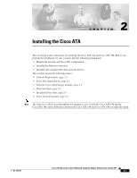
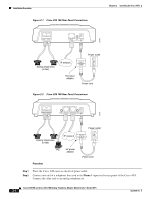
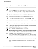
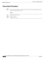
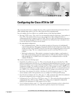
Installation Procedure Figure 2-1 Cisco ATA 186 Rear Panel Connections Chapter 2 Installing the Cisco ATA 72212 PHONE 1 PHONE 2 10BaseT ACT 5V Analog telephones (or fax) IP network 5V power adaptor Power outlet Power cord Figure 2-2 Cisco ATA 188 Rear Panel Connections 72213 PHONE 1 PHONE 2 LINK 10/100 PC 10/100 UPLINK LINK 5V Power outlet Analog telephones (or fax) IP network PC 5V power adaptor Procedure Power cord Step 1 Step 2 Place the Cisco ATA near an electrical power outlet. Connect one end of a telephone line cord to the Phone 1 input on the rear panel of the Cisco ATA. Connect the other end to an analog telephone set. Cisco ATA 186 and Cisco ATA 188 Analog Telephone Adaptor Administrator's Guide (SIP) 2-4 OL-3410-01
-
 1
1 -
2
-
3
-
4
-
5
-
6
-
7
-
8
-
9
-
10
-
11
-
12
-
13
-
14
-
15
-
16
-
17
-
18
-
19
-
20
-
21
-
22
-
23
-
24
-
25
-
26
-
 27
27 -
 28
28 -
 29
29 -
 30
30 -
 31
31 -
 32
32 -
 33
33 -
 34
34 -
 35
35 -
 36
36 -
 37
37 -
38
-
39
-
40
-
41
-
42
-
43
-
44
-
45
-
46
-
47
-
48
-
49
-
50
-
51
-
52
-
53
-
54
-
55
-
56
-
57
-
58
-
59
-
60
-
61
-
62
-
63
-
64
-
65
-
66
-
67
-
68
-
69
-
70
-
71
-
72
-
73
-
74
-
75
-
76
-
77
-
78
-
79
-
80
-
81
-
82
-
83
-
84
-
85
-
86
-
87
-
88
-
89
-
90
-
91
-
92
-
93
-
94
-
95
-
96
-
97
-
98
-
99
-
100
-
101
-
102
-
103
-
104
-
105
-
106
-
107
-
108
-
109
-
110
-
111
-
112
-
113
-
114
-
115
-
116
-
117
-
118
-
119
-
120
-
121
-
122
-
123
-
124
-
125
-
126
-
127
-
128
-
129
-
130
-
131
-
132
-
133
-
134
-
135
-
136
-
137
-
138
-
139
-
140
-
141
-
142
-
143
-
144
-
145
-
146
-
147
-
148
-
149
-
150
-
151
-
152
-
153
-
154
-
155
-
156
-
157
-
158
-
159
-
160
-
161
-
162
-
163
-
164
-
165
-
166
-
167
-
168
-
169
-
170
-
171
-
172
-
173
-
174
-
175
-
176
-
177
-
178
-
179
-
180
-
181
-
182
-
183
-
184
-
185
-
186
-
187
-
188
-
189
-
190
-
191
-
192
-
193
-
194
-
195
-
196
-
197
-
198
-
199
-
200
-
201
-
202
-
203
-
204
-
205
-
206
-
207
-
208
-
209
-
210
-
211
-
212
-
213
-
214
-
215
-
216
-
217
-
218
 |
 |
2-4
Cisco ATA 186 and Cisco ATA 188 Analog Telephone Adaptor Administrator’s Guide (SIP)
OL-3410-01
Chapter 2
Installing the Cisco ATA
Installation Procedure
Figure 2-1
Cisco ATA 186 Rear Panel Connections
Figure 2-2
Cisco ATA 188 Rear Panel Connections
Procedure
Step 1
Place the Cisco ATA near an electrical power outlet.
Step 2
Connect one end of a telephone line cord to the
Phone 1
input on the rear panel of the Cisco ATA.
Connect the other end to an analog telephone set.
Power outlet
10BaseT
ACT
5V
PHONE 1
PHONE 2
72212
Analog telephones
(or fax)
5V power
adaptor
Power cord
IP network
10/100 UPLINK
10/100 PC
LINK
LINK
5V
PHONE 1
PHONE 2
Power outlet
72213
Analog telephones
(or fax)
5V power
adaptor
Power cord
PC
IP network