Compaq 100B Maintenance & Service Guide 100B SFF PC - Page 42
Front I/O Assembly
 |
View all Compaq 100B manuals
Add to My Manuals
Save this manual to your list of manuals |
Page 42 highlights
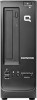
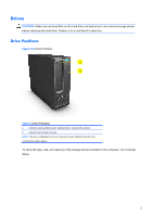
Front I/O Assembly The front I/O assembly is attached to the front of the chassis. Pull the assembly away from the chassis to remove it. 1. Prepare the computer for disassembly (Preparation for Disassembly on page 22). 2. Remove the access panel (Access Panel on page 23). 3. Remove the front bezel (Front Bezel on page 24). 4. Disconnect the front audio and front USB cables from the yellow and white system board connectors. 5. Remove the cables from the clips on the base of the computer chassis, see Fig. 6-11 for details. Figure 5-11 Front I/O assembly cable clip locations 6. Remove the screw that secures the assembly to the front of the chassis (1). 7. Slide the assembly up and pull it away from the front of the chassis while threading the wires through the hole in the chassis (2). Figure 5-12 Removing the front I/O assembly To install the front I/O assembly, reverse the removal procedure. NOTE: Be sure to correctly route the cables when reinstalling the assembly. Proper cable routing prevents damage to the cables and promotes proper air flow. 34
-
 1
1 -
2
-
3
-
4
-
5
-
6
-
7
-
8
-
9
-
10
-
11
-
12
-
13
-
14
-
15
-
16
-
17
-
18
-
19
-
20
-
21
-
22
-
23
-
24
-
25
-
26
-
27
-
28
-
29
-
30
-
31
-
32
-
33
-
34
-
35
-
36
-
 37
37 -
 38
38 -
 39
39 -
 40
40 -
 41
41 -
 42
42 -
 43
43 -
 44
44 -
 45
45 -
 46
46 -
 47
47 -
48
-
49
-
50
-
51
-
52
-
53
-
54
-
55
-
56
-
57
-
58
-
59
-
60
-
61
-
62
-
63
-
64
-
65
-
66
-
67
-
68
-
69
-
70
-
71
-
72
-
73
-
74
-
75
-
76
-
77
-
78
-
79
-
80
-
81
-
82
-
83
-
84
-
85
-
86
-
87
-
88
-
89
-
90
-
91
-
92
-
93
-
94
-
95
-
96
-
97
-
98
-
99
-
100
-
101
-
102
-
103
-
104
 |
 |
