Compaq Evo n600c Maintenance and Service Guide Compaq Evo N600c - Page 75
Disassembly Sequence Chart
 |
View all Compaq Evo n600c manuals
Add to My Manuals
Save this manual to your list of manuals |
Page 75 highlights
Removal and Replacement Procedures 5.2 Disassembly Sequence Chart Use the chart below to determine the section number to be referenced when removing computer components. Table 5-1 Disassembly Sequence Chart Section 5.3 5.4 5.5 5.6 5.7 5.8 5.9 5.10 5.11 5.12 5.13 5.14 5.15 Description Preparing the computer for disassembly Computer feet Keyboard Modem/Network Interface Card (NIC) Real Time Clock (RTC) battery TouchPad and Touch button Switch cover Display Top cover System board Fan DC-DC converter board Modem cable # of Screws Removed 0 0 1 0 0 0 2 3 10 5 2 0 0 Maintenance and Service Guide 5-3
-
 1
1 -
2
-
3
-
4
-
5
-
6
-
7
-
8
-
9
-
10
-
11
-
12
-
13
-
14
-
15
-
16
-
17
-
18
-
19
-
20
-
21
-
22
-
23
-
24
-
25
-
26
-
27
-
28
-
29
-
30
-
31
-
32
-
33
-
34
-
35
-
36
-
37
-
38
-
39
-
40
-
41
-
42
-
43
-
44
-
45
-
46
-
47
-
48
-
49
-
50
-
51
-
52
-
53
-
54
-
55
-
56
-
57
-
58
-
59
-
60
-
61
-
62
-
63
-
64
-
65
-
66
-
67
-
68
-
69
-
 70
70 -
 71
71 -
 72
72 -
 73
73 -
 74
74 -
 75
75 -
 76
76 -
 77
77 -
 78
78 -
 79
79 -
 80
80 -
81
-
82
-
83
-
84
-
85
-
86
-
87
-
88
-
89
-
90
-
91
-
92
-
93
-
94
-
95
-
96
-
97
-
98
-
99
-
100
-
101
-
102
-
103
-
104
-
105
-
106
-
107
-
108
-
109
-
110
-
111
-
112
-
113
-
114
-
115
-
116
-
117
-
118
-
119
-
120
-
121
-
122
-
123
-
124
-
125
-
126
-
127
-
128
-
129
-
130
-
131
-
132
-
133
-
134
-
135
-
136
-
137
-
138
-
139
-
140
-
141
-
142
-
143
-
144
-
145
-
146
-
147
-
148
-
149
-
150
-
151
-
152
 |
 |
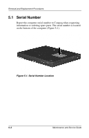
Removal and Replacement Procedures
Maintenance and Service Guide
5
–
3
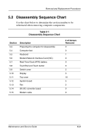
5.2
Disassembly Sequence Chart
Use the chart below to determine the section number to be
referenced when removing computer components.
Table 5-1
Disassembly Sequence Chart
Section
Description
# of Screws
Removed
5.3
Preparing the computer for disassembly
0
5.4
Computer feet
0
5.5
Keyboard
1
5.6
Modem/Network Interface Card (NIC)
0
5.7
Real Time Clock (RTC) battery
0
5.8
TouchPad and Touch button
0
5.9
Switch cover
2
5.10
Display
3
5.11
Top cover
10
5.12
System board
5
5.13
Fan
2
5.14
DC-DC converter board
0
5.15
Modem cable
0