Compaq Evo n600c Maintenance and Service Guide Compaq Evo N600c - Page 87
Switch Cover
 |
View all Compaq Evo n600c manuals
Add to My Manuals
Save this manual to your list of manuals |
Page 87 highlights
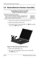
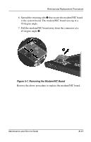
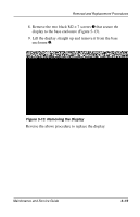
Removal and Replacement Procedures 5.9 Switch Cover Switch Cover Spare Part Number Information Switch cover 241438-001 1. Prepare the computer for disassembly (Section 5.3). 2. Remove the keyboard (Section 5.5). 3. Position the computer so the rear panel faces you. 4. Remove the two black M2 × 7 screws that secure the switch cover to the base enclosure (Figure 5-10). Figure 5-10. Removing the Switch Cover Screws 5. Position the computer so the front faces you. 6. Open the computer as far as it will open. Maintenance and Service Guide 5-15
-
 1
1 -
2
-
3
-
4
-
5
-
6
-
7
-
8
-
9
-
10
-
11
-
12
-
13
-
14
-
15
-
16
-
17
-
18
-
19
-
20
-
21
-
22
-
23
-
24
-
25
-
26
-
27
-
28
-
29
-
30
-
31
-
32
-
33
-
34
-
35
-
36
-
37
-
38
-
39
-
40
-
41
-
42
-
43
-
44
-
45
-
46
-
47
-
48
-
49
-
50
-
51
-
52
-
53
-
54
-
55
-
56
-
57
-
58
-
59
-
60
-
61
-
62
-
63
-
64
-
65
-
66
-
67
-
68
-
69
-
70
-
71
-
72
-
73
-
74
-
75
-
76
-
77
-
78
-
79
-
80
-
81
-
 82
82 -
 83
83 -
 84
84 -
 85
85 -
 86
86 -
 87
87 -
 88
88 -
 89
89 -
 90
90 -
 91
91 -
 92
92 -
93
-
94
-
95
-
96
-
97
-
98
-
99
-
100
-
101
-
102
-
103
-
104
-
105
-
106
-
107
-
108
-
109
-
110
-
111
-
112
-
113
-
114
-
115
-
116
-
117
-
118
-
119
-
120
-
121
-
122
-
123
-
124
-
125
-
126
-
127
-
128
-
129
-
130
-
131
-
132
-
133
-
134
-
135
-
136
-
137
-
138
-
139
-
140
-
141
-
142
-
143
-
144
-
145
-
146
-
147
-
148
-
149
-
150
-
151
-
152
 |
 |

Removal and Replacement Procedures
Maintenance and Service Guide
5
–
15
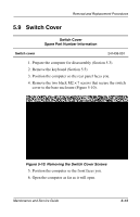
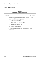
5.9
Switch Cover
1. Prepare the computer for disassembly (Section 5.3).
2. Remove the keyboard (Section 5.5).
3. Position the computer so the rear panel faces you.
4. Remove the two black M2
×
7 screws that secure the switch
cover to the base enclosure (Figure 5-10).
Figure 5-10. Removing the Switch Cover Screws
5. Position the computer so the front faces you.
6. Open the computer as far as it will open.
Switch Cover
Spare Part Number Information
Switch cover
241438-001