Compaq Presario 17XL Presario NA1700XL Series Maintenance and Service Guide - Page 96
Processor
 |
View all Compaq Presario 17XL manuals
Add to My Manuals
Save this manual to your list of manuals |
Page 96 highlights
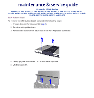
Presario 1700 Series Models: XL260, XL261, XL262, XL264, XL265, XL266, XL274, XL275, XL360, XL361, XL362, XL363, XL364, XL365, XL366, XL367, XL368, XL369, XL370, XL371, XL372, XL373, XL374, XL375, XL376, XL377, and XL378 Processor To remove the processor, complete the following steps: 1. Prepare the unit for disassembly(pg 7). 2. Remove the LED button bezel (pg 12). 3. Remove the keyboard (pg 14). 4. Remove the Heatspreader (pg 15). 5. Remove the Heatsink assembly (pg 16). 6. Turn screw counter-clockwise (1/2 turn only), then lift the processor and remove it from the socket. ÄCAUTION: If you turn the screw more than a half turn, you will damage the socket, making it necessary to replace the system board.
-
 1
1 -
2
-
3
-
4
-
5
-
6
-
7
-
8
-
9
-
10
-
11
-
12
-
13
-
14
-
15
-
16
-
17
-
18
-
19
-
20
-
21
-
22
-
23
-
24
-
25
-
26
-
27
-
28
-
29
-
30
-
31
-
32
-
33
-
34
-
35
-
36
-
37
-
38
-
39
-
40
-
41
-
42
-
43
-
44
-
45
-
46
-
47
-
48
-
49
-
50
-
51
-
52
-
53
-
54
-
55
-
56
-
57
-
58
-
59
-
60
-
61
-
62
-
63
-
64
-
65
-
66
-
67
-
68
-
69
-
70
-
71
-
72
-
73
-
74
-
75
-
76
-
77
-
78
-
79
-
80
-
81
-
82
-
83
-
84
-
85
-
86
-
87
-
88
-
89
-
90
-
 91
91 -
 92
92 -
 93
93 -
 94
94 -
 95
95 -
 96
96 -
 97
97 -
 98
98 -
 99
99 -
 100
100 -
 101
101 -
102
-
103
-
104
-
105
-
106
-
107
-
108
-
109
-
110
-
111
-
112
-
113
-
114
-
115
-
116
-
117
-
118
-
119
-
120
-
121
-
122
-
123
-
124
-
125
-
126
-
127
-
128
-
129
-
130
-
131
-
132
-
133
-
134
-
135
 |
 |

Presario 1700 Series
Models: XL260, XL261, XL262, XL264, XL265, XL266, XL274, XL275, XL360, XL361,
XL362, XL363, XL364, XL365, XL366, XL367, XL368, XL369, XL370, XL371, XL372, XL373,
XL374, XL375, XL376, XL377, and XL378
Processor
To remove the processor, complete the following steps:
1.
Prepare the unit for disassembly(
pg 7
).
2.
Remove the LED button bezel (
pg 12
).
3.
Remove the keyboard (
pg 14
).
4.
Remove the Heatspreader (
pg 15
).
5.
Remove the Heatsink assembly (
pg 16
).
6.
Turn screw
counter-clockwise (1/2 turn
only
), then lift the processor
and
remove it from the socket.
Ä
CAUTION:
If you turn the screw more than a half turn, you will damage the
socket, making it necessary to replace the system board.