Compaq nc8000 HP Compaq nc8000 Business PC, HP Compaq nw8000 Mobile Workstatio - Page 139
System Board
 |
View all Compaq nc8000 manuals
Add to My Manuals
Save this manual to your list of manuals |
Page 139 highlights
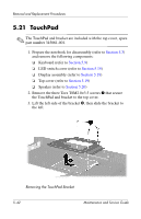
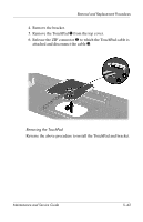
Removal and Replacement Procedures 5.23 System Board Spare Part Number Information System board with 128 MB of video memory System board with 64 MB of video memory ✎ Both system boards include thermal grease. 349206-001 345064-001 ✎ When replacing the system board, ensure that the following components are removed from the defective system board and installed on the replacement system board: ■ Memory expansion boards (refer to Section 5.10) ■ Modem board (refer to Section 5.11) ■ Mini PCI communications board (refer to Section 5.12) ■ Heat sink (refer to Section 5.13) ■ Processor (refer to Section 5.14) ■ Real time clock battery (refer to Section 5.16) ■ Security card (refer to Section 5.17) 1. Prepare the notebook for disassembly (refer to Section 5.3) and remove the following components: ❏ Keyboard (refer to Section 5.9) ❏ LED switch cover (refer to Section 5.15) ❏ Display assembly (refer to Section 5.18) ❏ Top cover (refer to Section 5.19) ❏ Fan (refer to Section 5.22) 5-46 Maintenance and Service Guide
-
 1
1 -
2
-
3
-
4
-
5
-
6
-
7
-
8
-
9
-
10
-
11
-
12
-
13
-
14
-
15
-
16
-
17
-
18
-
19
-
20
-
21
-
22
-
23
-
24
-
25
-
26
-
27
-
28
-
29
-
30
-
31
-
32
-
33
-
34
-
35
-
36
-
37
-
38
-
39
-
40
-
41
-
42
-
43
-
44
-
45
-
46
-
47
-
48
-
49
-
50
-
51
-
52
-
53
-
54
-
55
-
56
-
57
-
58
-
59
-
60
-
61
-
62
-
63
-
64
-
65
-
66
-
67
-
68
-
69
-
70
-
71
-
72
-
73
-
74
-
75
-
76
-
77
-
78
-
79
-
80
-
81
-
82
-
83
-
84
-
85
-
86
-
87
-
88
-
89
-
90
-
91
-
92
-
93
-
94
-
95
-
96
-
97
-
98
-
99
-
100
-
101
-
102
-
103
-
104
-
105
-
106
-
107
-
108
-
109
-
110
-
111
-
112
-
113
-
114
-
115
-
116
-
117
-
118
-
119
-
120
-
121
-
122
-
123
-
124
-
125
-
126
-
127
-
128
-
129
-
130
-
131
-
132
-
133
-
 134
134 -
 135
135 -
 136
136 -
 137
137 -
 138
138 -
 139
139 -
 140
140 -
 141
141 -
 142
142 -
 143
143 -
 144
144 -
145
-
146
-
147
-
148
-
149
-
150
-
151
-
152
-
153
-
154
-
155
-
156
-
157
-
158
-
159
-
160
-
161
-
162
-
163
-
164
-
165
-
166
-
167
-
168
-
169
-
170
-
171
-
172
-
173
-
174
-
175
-
176
-
177
-
178
-
179
-
180
-
181
-
182
-
183
-
184
-
185
-
186
-
187
-
188
-
189
 |
 |