Craftsman 28933 Operation Manual - Page 120
to lowerthe frontof the deck.
 |
View all Craftsman 28933 manuals
Add to My Manuals
Save this manual to your list of manuals |
Page 120 highlights
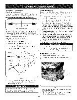
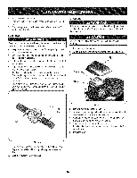
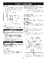
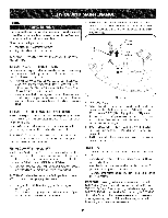
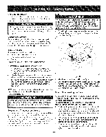
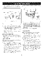
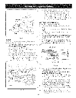
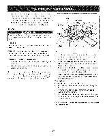
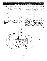
4. Workingfrom the left side of the tractor,loosen,but do not f remove,the hexcap screwin the left deck adjustmentbracket. See Figure15. AdjustmentGear )eck of Deck Hex CapScrew Figure15 5. Toeventhe deck turnthe adjustmentgear,locatedimmediately behindthe hexcap screw,clockwise(rearward)to lowerthe left sideof the deck.Turnthe gear counter-clockwise(towardfront) to raisethe left sideof the deck.See Figure15. 6. Thedeck is properlyleveledwhenbothblade tip measurements, as describedearlier,are equal. 7. Retightenthe hexcap screwin the left deck adjustmentbracket whenproperadjustmentis achieved. Front To Rear Deck Leveling Thefront of the cuttingdeck issupportedby an adjustablefrontdeck hangerrod.This rod canbe adjustedto set the front to rear pitch of thedeck. Thefront of the deck shouldbe approximately1/4-inchlower thanthe rear of the deck. Adjustif necessaryas follows: NOTE:Thedeck shouldfirst be leveledsideto side.Checkthe sideto side levelof the deck and adjust if necessary. 1. Withthe tractorparkedon a firm,levelsurface,movethe deckto the midheightposition(thirdor fourthnotch) usingthedeck lift lever.Carefullyrotatethe RH blade(nearestthe dischargechute) so that it is parallelwith the tractorframe. 2. Measurethe distancefrom the frontof the bladetip to the ground and the rear of the bladetip to the ground.The front measurementtaken shouldbe approximately1/4"less thanthe rear measurementD. eterminewhetherthefront of the deck hasto be raisedor lowered. 3. Workingat the front of the tractor,loosenthe two hex lock nutsat thefront of the deck hangerrod. Threadthe lock nuts awayfrom the hexnuts behindthem.Referto Figure16. Figure16 4. Usea open end wrenchto turnthe inner hexnuts to adjustthe front of the deck.Turnthe hexnuts clockwiseto raisethe front of the deck,or counterclockwiseto lowerthe front of the deck. Adjustthe hexnutsevenly sothat the deck hangerrod isat the front of both slotsin the hangerbracketon the frontof the deck. See Figure16. 5. Refightenthe two hex lock nutswhenproperlyadjusted. Deck Gauge Wheel NOTE:The deck gaugewheelsare an anti-scalpfeatureof the deck and are notdesignedto supportthe weightof the cuttingdeck. The deck gaugewheelsshouldneithercontactthe ground,nor be high off the ground,whenthe deck is movedto thedesiredheightsetting.If you changeyourcuttingheightduringthe mowingseason,the gauge wheels shouldbe checkedand adjustedas necessary. Adjustthe gauge wheelsasfollows: 1. Placethe tractoron a fiat surfaceand movethe deck to the desiredmowingheightusingthe deck lift lever. 2. Checkgaugewheelsdistancefromthe flat surfacebelow.If the gaugewheelscontact theground,they mustbe raised.If the gaugewheelsare higherthan 1/2"abovethe ground,they should be lowered. 3. Removethe hexflangelock nut and shoulderbolt securingone of the front gaugewheelsto the front indexbracket.Repositionthe gaugewheelto alignwith the one of five indexholesthat places the wheel 1/4"to 1/2" abovethe ground.Securethegauge wheel to the indexbracketwith the shoulderbolt and flangelock nut. Notethe indexhole usedand securethe othergauge wheelin the sameposition.See Figure17. 24
-
 1
1 -
2
-
3
-
4
-
5
-
6
-
7
-
8
-
9
-
10
-
11
-
12
-
13
-
14
-
15
-
16
-
17
-
18
-
19
-
20
-
21
-
22
-
23
-
24
-
25
-
26
-
27
-
28
-
29
-
30
-
31
-
32
-
33
-
34
-
35
-
36
-
37
-
38
-
39
-
40
-
41
-
42
-
43
-
44
-
45
-
46
-
47
-
48
-
49
-
50
-
51
-
52
-
53
-
54
-
55
-
56
-
57
-
58
-
59
-
60
-
61
-
62
-
63
-
64
-
65
-
66
-
67
-
68
-
69
-
70
-
71
-
72
-
73
-
74
-
75
-
76
-
77
-
78
-
79
-
80
-
81
-
82
-
83
-
84
-
85
-
86
-
87
-
88
-
89
-
90
-
91
-
92
-
93
-
94
-
95
-
96
-
97
-
98
-
99
-
100
-
101
-
102
-
103
-
104
-
105
-
106
-
107
-
108
-
109
-
110
-
111
-
112
-
113
-
114
-
 115
115 -
 116
116 -
 117
117 -
 118
118 -
 119
119 -
 120
120 -
 121
121 -
 122
122 -
 123
123 -
 124
124 -
 125
125 -
126
-
127
-
128
-
129
-
130
-
131
-
132
-
133
-
134
-
135
-
136
-
137
-
138
-
139
-
140
-
141
-
142
-
143
-
144
-
145
-
146
-
147
-
148
-
149
-
150
-
151
-
152
-
153
-
154
-
155
-
156
-
157
-
158
-
159
-
160
-
161
-
162
-
163
-
164
-
165
-
166
-
167
-
168
-
169
-
170
-
171
-
172
-
173
-
174
-
175
-
176
-
177
-
178
-
179
-
180
-
181
-
182
-
183
-
184
-
185
-
186
-
187
-
188
-
189
-
190
-
191
-
192
 |
 |
