Craftsman 28933 Operation Manual - Page 122
Spring& Screw
 |
View all Craftsman 28933 manuals
Add to My Manuals
Save this manual to your list of manuals |
Page 122 highlights
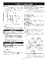
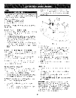
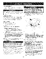
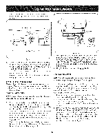
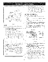
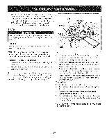
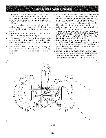
BLADES Be sureto shutthe engineoff, removeignitionkey,disconnectthe sparkplug wire(s) to preventunintendedstartingbeforeremovingthe cuttingblade(s)for sharpeningor replacement.Protectyourhands b_ usng heavyg oves or a rag to graspthecutt ng bade. The bladesmay be removedas follows: 1. Removethe deck from beneaththe tractor,(referto CuttingDeck Removal)then gentlyflip the deckoverto exposeits underside. . It is importantthat each cuttingbladeedge be groundequallyto maintainproperblade balance. 7. A poorlybalancedbladewill causeexcessivevibrationand may causedamageto the tractorand resultin personalinjury.The blade can be testedby balancingit on a round shaftscrewdriver. Grind metalfrom the heavyside untilit balancesevenly. iMPORTANTW: hen replacingthe blades,makecertain the sideof the blade marked"Bottom" facesthegroundwhenthe moweris turnedto the operatingposition. NOTE:Placea blockof woodbetweenthedeck housingand the cuttingedgeof the bladeto help in breakingloosethehex nut securing the blade. 2. Use a 15/16"wrenchto loosenthehex flangenutsecuringthe bladeto the bottomof the spindleassembly.Securethe spindle by eitherholdingthe bladetightly,or by usinga secondwrenchto hold the nutat the top of the spindle. 3. Continueholdingthe blade ontothe star hub of the spindle,and removethe flangenut and cuttingblade. 4. Repeatthepreviousstepsto removethe otherblade. 5. Toproperlysharpenthe cuttingblades,removeequal amounts of metalfrom bothends of the bladesalong thecuttingedges, parallelto the trailingedge,at a 250to 300angle. iMPORTANT:ifthecuttingedge of the blade hasalreadybeen sharpenedto within 1-5/8"width from theoppositeedge,or if any metal separationis present,replacethe bladeswith newones.See Figure20. f iMPORTANT:Notethat the starsof the blades(and spindles)are not symmetrical.The bladecan be installedon each spindlein onlyone direction.Carefullyalign the star holeof theblade with the star of the spindleshaftwheninstallingeachblade.DO NOTimproperlyalignthe blade and spindleshaft,and attemptto seat the bladeontothe spindle by tighteningthe hexflange nut. 8. Rotatethe bladeas necessaryto align its star hole with the star of the spindleshaft,then slidethe blade ontothe spindleshaft. Threadthe hexflangeontothe spindleshaft and usea torque wrenchto tightenthe hex flangenutto 70 to 90 foot-pounds. 9. Repeatthe aboveprocedureto installthe other blade. Checking Blade Timing Duringnormaloperationthe timingof the cuttingbladescan be altered by abnormalloadson one, or both, cuttingblades.Regularlycheckthe timing arrowson the spindleassembliesto makecertain they are 900 from eachother. If the timingarrowsare not 900from eachother,proceedas follows: 1. Removethe deck fromthe tractor.Removethe idler bracket _aration backstop.Referto Figure21. f ) lind Wing SharpenEdge Evenly 1-5/8inch Figure 20 Bracket Backstop Idler Bracket& Idler Pulley Spring& Screw Figure21 26
-
 1
1 -
2
-
3
-
4
-
5
-
6
-
7
-
8
-
9
-
10
-
11
-
12
-
13
-
14
-
15
-
16
-
17
-
18
-
19
-
20
-
21
-
22
-
23
-
24
-
25
-
26
-
27
-
28
-
29
-
30
-
31
-
32
-
33
-
34
-
35
-
36
-
37
-
38
-
39
-
40
-
41
-
42
-
43
-
44
-
45
-
46
-
47
-
48
-
49
-
50
-
51
-
52
-
53
-
54
-
55
-
56
-
57
-
58
-
59
-
60
-
61
-
62
-
63
-
64
-
65
-
66
-
67
-
68
-
69
-
70
-
71
-
72
-
73
-
74
-
75
-
76
-
77
-
78
-
79
-
80
-
81
-
82
-
83
-
84
-
85
-
86
-
87
-
88
-
89
-
90
-
91
-
92
-
93
-
94
-
95
-
96
-
97
-
98
-
99
-
100
-
101
-
102
-
103
-
104
-
105
-
106
-
107
-
108
-
109
-
110
-
111
-
112
-
113
-
114
-
115
-
116
-
 117
117 -
 118
118 -
 119
119 -
 120
120 -
 121
121 -
 122
122 -
 123
123 -
 124
124 -
 125
125 -
 126
126 -
 127
127 -
128
-
129
-
130
-
131
-
132
-
133
-
134
-
135
-
136
-
137
-
138
-
139
-
140
-
141
-
142
-
143
-
144
-
145
-
146
-
147
-
148
-
149
-
150
-
151
-
152
-
153
-
154
-
155
-
156
-
157
-
158
-
159
-
160
-
161
-
162
-
163
-
164
-
165
-
166
-
167
-
168
-
169
-
170
-
171
-
172
-
173
-
174
-
175
-
176
-
177
-
178
-
179
-
180
-
181
-
182
-
183
-
184
-
185
-
186
-
187
-
188
-
189
-
190
-
191
-
192
 |
 |
