Cub Cadet LTX 1045 Operation Manual - Page 27
artery - blade removal
 |
View all Cub Cadet LTX 1045 manuals
Add to My Manuals
Save this manual to your list of manuals |
Page 27 highlights
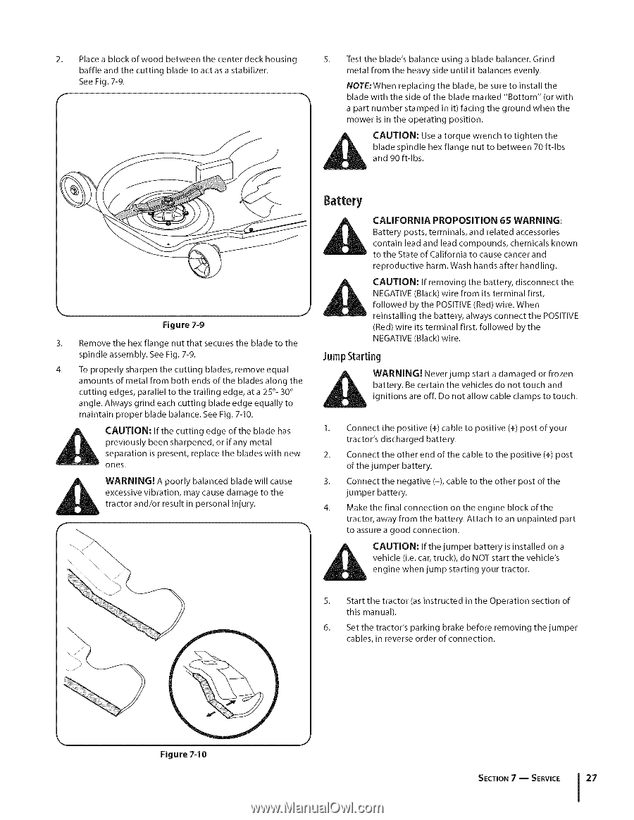
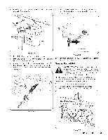
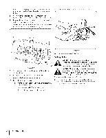
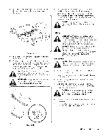
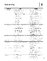
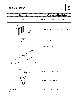
2. Place a block of wood between the center deck housing baffle and the cutting blade to act as a stabilizer. See Fig. 7-9. 5. Test the blade's balance using a blade balancer. Grind metal from the heavy side until it balances evenly. NOTE:When replacing the blade, be sure to install the blade with the side of the blade marked "Bottom" (or with a part number stamped in it) facing the ground when the mower is in the operating position. blade spindle hex flange nut to between 70 ft-lbs CanAd U9T0IOft-lNbs:. Use a torque wrench to tighten the Figure 7-9 3. Remove the hex flange nut that secures the blade to the spindle assembly. See Fig. 7-9. 4. To properly sharpen the cutting blades, remove equal amounts of metal from both ends of the blades along the cutting edges, parallel to the trailing edge, at a 25 °- 30 ° angle. Always grind each cutting blade edge equally to maintain proper blade balance. See Fig. 7-10. CAUTION: If the cutting edge of the blade has previously been sharpened, or if any metal separation is present, replace the blades with new ones. WARNING! A poorly balanced blade will cause excessive vibration, may cause damage to the tractor and/or result in personal injury. 8artery CALIFORNIA PROPOSiTiON 65 WARNING: Battery posts, terminals, and related accessories contain lead and lead compounds, chemicals known to the State of California to cause cancer and reproductive harm. Wash hands after handling. CAUTION: If removing the battery, disconnect the NEGATIVE (Black) wire from its terminal first, followed by the POSITIVE (Red) wire. When reinstalling the battery, always connect the POSITIVE (Red) wire its terminal first, followed by the NEGATIVE (Black) wire. Jump Starting battery. Be certain the vehicles do not touch and i_ll WignAiRtioNnIsNG!are oNffe.veDrojunmopt alslotawrt caabdleamaclgaemdps ortofrotozuecnh. 1. Connect the positive (+) cable to positive (+) post of your tractor's discharged battery. 2. Connect the other end of the cable to the positive (+) post of the jumper battery. 3. Connect the negative (-), cable to the other post of the jumper battery. 4. Make the final connection on the engine block of the tractor, away from the battery. Attach to an unpainted part to assure a good connection. _hL vehicle (i.e. car, truck), do NOT start the vehicle's enAginUeTIOwhNe:n Ifjuthmep jumstpaertring bayttoeuryr triascitnosr.talled on a 5. Start the tractor (as instructed in the Operation section of this manual). 6. Set the tractor's parking brake before removing the jumper cables, in reverse order of connection. Figure 7-10 SECTION7 -- SERVICE 27
-
 1
1 -
2
-
3
-
4
-
5
-
6
-
7
-
8
-
9
-
10
-
11
-
12
-
13
-
14
-
15
-
16
-
17
-
18
-
19
-
20
-
21
-
 22
22 -
 23
23 -
 24
24 -
 25
25 -
 26
26 -
 27
27 -
 28
28 -
 29
29 -
 30
30 -
 31
31 -
 32
32 -
33
-
34
-
35
-
36
-
37
-
38
-
39
-
40
-
41
-
42
-
43
-
44
-
45
-
46
-
47
-
48
-
49
-
50
-
51
-
52
-
53
-
54
-
55
-
56
-
57
-
58
-
59
-
60
-
61
-
62
-
63
-
64
-
65
-
66
-
67
-
68
-
69
-
70
-
71
-
72
-
73
-
74
-
75
-
76
-
77
-
78
-
79
-
80
-
81
-
82
-
83
-
84
-
85
-
86
-
87
-
88
-
89
-
90
-
91
-
92
-
93
-
94
-
95
-
96
-
97
-
98
-
99
-
100
-
101
-
102
-
103
-
104
-
105
-
106
-
107
-
108
-
109
-
110
-
111
-
112
-
113
-
114
-
115
-
116
-
117
-
118
-
119
-
120
-
121
-
122
-
123
-
124
-
125
-
126
-
127
-
128
-
129
-
130
-
131
-
132
-
133
-
134
-
135
-
136
-
137
-
138
-
139
-
140
-
141
-
142
-
143
-
144
 |
 |