Cub Cadet LTX 1045 Operation Manual - Page 94
DeckSpindle, the DeckFrontTo Rear - deck spindle
 |
View all Cub Cadet LTX 1045 manuals
Add to My Manuals
Save this manual to your list of manuals |
Page 94 highlights
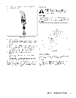
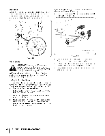
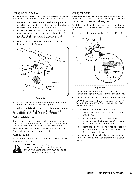
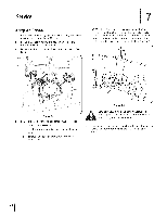
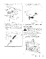
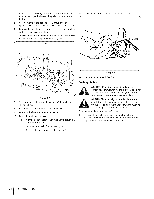
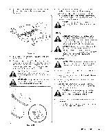
DeckSpindle Grease fittings can be found on each deck spindle. See Fig. 6-4. Lubricate with 251H EP grease or an equivalent No. 2 multipurpose lithium grease. Using a grease gun, apply two strokes (minimum) or sufficient grease to the spindle shaft. Determine the approximate distance necessary for proper adjustment and proceed, if necessary. 1. Loosen (thread outward) the hex lock nut on the end of the deck hanger rod. See Fig. 6-5. f Figure 6-4 Adjustments WARNING! Shut the engine off, remove the ignition key and engage the parking brake before making adjustments. Protect your hands by using heavy gloves when handling the blades. NOTE: Check the tractor's tire pressure before performing any deck leveling adjustments. Refer to Tires on page 27 for information regarding tire pressure. J Figure 6-5 2. To raise the front of the deck, tighten (thread inward) the inner hex nut against the front hanger bracket. 3. To Iowerthe front of the deck, loosen (thread outward) the hex nut, away from the front hanger bracket. See Fig. 6-5. 4. Retighten the lock nut against each hex nut when proper adjustment is achieved. Levelingthe Deck(Front To Rear) The front of the cutting deck is supported by a stabilizer bar that can be adjusted to level the deck from front to rear. The front of the deck should be between 1/4-inch and %-inch lower than the rear of the deck. Adjust if necessary as follows: 1. Park the tractor on a firm, level surface and place the deck lift lever in the middle position. 2. Rotate the blade nearest the discharge chute so that it is parallel with the tractor. 3. Measure the distance from the front of the blade tip to the ground and the rear of the blade tip to the ground. The first measurement taken should be between 1/4"and %" less than the second measurement. SECTION 6 -- MAINTENANCE & ADJUSTMENTS
-
 1
1 -
2
-
3
-
4
-
5
-
6
-
7
-
8
-
9
-
10
-
11
-
12
-
13
-
14
-
15
-
16
-
17
-
18
-
19
-
20
-
21
-
22
-
23
-
24
-
25
-
26
-
27
-
28
-
29
-
30
-
31
-
32
-
33
-
34
-
35
-
36
-
37
-
38
-
39
-
40
-
41
-
42
-
43
-
44
-
45
-
46
-
47
-
48
-
49
-
50
-
51
-
52
-
53
-
54
-
55
-
56
-
57
-
58
-
59
-
60
-
61
-
62
-
63
-
64
-
65
-
66
-
67
-
68
-
69
-
70
-
71
-
72
-
73
-
74
-
75
-
76
-
77
-
78
-
79
-
80
-
81
-
82
-
83
-
84
-
85
-
86
-
87
-
88
-
 89
89 -
 90
90 -
 91
91 -
 92
92 -
 93
93 -
 94
94 -
 95
95 -
 96
96 -
 97
97 -
 98
98 -
 99
99 -
100
-
101
-
102
-
103
-
104
-
105
-
106
-
107
-
108
-
109
-
110
-
111
-
112
-
113
-
114
-
115
-
116
-
117
-
118
-
119
-
120
-
121
-
122
-
123
-
124
-
125
-
126
-
127
-
128
-
129
-
130
-
131
-
132
-
133
-
134
-
135
-
136
-
137
-
138
-
139
-
140
-
141
-
142
-
143
-
144
 |
 |
