Dell Alienware 13 R3 Service Manual - Page 74
Replacing the display assembly, Procedure, Post-requisites
 |
View all Dell Alienware 13 R3 manuals
Add to My Manuals
Save this manual to your list of manuals |
Page 74 highlights
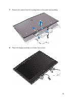
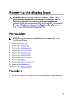
Replacing the display assembly WARNING: Before working inside your computer, read the safety information that shipped with your computer and follow the steps in Before working inside your computer. After working inside your computer, follow the instructions in After working inside your computer. For more safety best practices, see the Regulatory Compliance home page at www.dell.com/regulatory_compliance. Procedure 1 Route the cables through the routing holes on the palm-rest assembly. 2 Align the screw holes on the display hinges with the screw holes on the palm- rest assembly. 3 Replace the four screws (M2.5x6L) that secure the display assembly to the palm-rest assembly. 4 Turn the computer over. 5 Route the display cable through the routing guides on the palm-rest assembly. 6 Route the logo-board cable through the routing guides on the palm-rest assembly. 7 Route the antenna cables through the routing guides on the palm-rest assembly. Post-requisites 1 Replace the system board. 2 Replace the battery. 3 Replace the heat-sink assembly. 4 Replace the coin-cell battery. 5 Replace the computer base. 6 Replace the rear-I/O cover. 7 Replace the memory modules. 8 Replace the solid-state drive. 74
-
 1
1 -
2
-
3
-
4
-
5
-
6
-
7
-
8
-
9
-
10
-
11
-
12
-
13
-
14
-
15
-
16
-
17
-
18
-
19
-
20
-
21
-
22
-
23
-
24
-
25
-
26
-
27
-
28
-
29
-
30
-
31
-
32
-
33
-
34
-
35
-
36
-
37
-
38
-
39
-
40
-
41
-
42
-
43
-
44
-
45
-
46
-
47
-
48
-
49
-
50
-
51
-
52
-
53
-
54
-
55
-
56
-
57
-
58
-
59
-
60
-
61
-
62
-
63
-
64
-
65
-
66
-
67
-
68
-
 69
69 -
 70
70 -
 71
71 -
 72
72 -
 73
73 -
 74
74 -
 75
75 -
 76
76 -
 77
77 -
 78
78 -
 79
79 -
80
-
81
-
82
-
83
-
84
-
85
-
86
-
87
-
88
-
89
-
90
-
91
-
92
-
93
-
94
-
95
-
96
-
97
-
98
-
99
-
100
-
101
-
102
-
103
-
104
-
105
-
106
-
107
-
108
-
109
-
110
-
111
-
112
-
113
-
114
-
115
-
116
 |
 |