Dell Alienware x16 R2 Owners Manual - Page 101
rear I/O-cover, procedure and avoids breaking the thermal bond between the system board and heat sink.
 |
View all Dell Alienware x16 R2 manuals
Add to My Manuals
Save this manual to your list of manuals |
Page 101 highlights
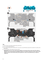
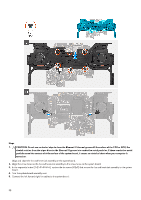
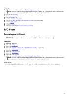
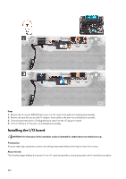
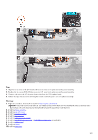
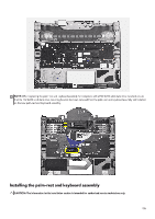
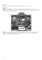
Steps 1. Align the screw holes on the I/O board with the screw holes on the palm-rest and keyboard assembly. 2. Replace the four screws (M2x2.5) that secure the I/O board to the palm-rest and keyboard assembly. 3. Connect and remove the I/O daughter board cable from the I/O daughter board. 4. Adhere the tape that secures the I/O daughter board cable to the palm-rest and keyboard assembly. Next steps 1. Follow the procedure from step 5 to step 20 in Replacing the system board. NOTE: The system board can be removed and installed along with the heat sink. This simplifies the removal and installation procedure and avoids breaking the thermal bond between the system board and heat sink. 2. Install the display assembly. 3. Install the rear I/O-cover. 4. Install the graphics-card fan. 5. Install the processor fan. 6. Install the solid state drive bracket. 7. Install the M.2 2230 solid state drive or M.2 2280 solid state drive, as applicable. 8. Install the wireless card. 9. Install the battery. 10. Install the base cover. 101
-
 1
1 -
2
-
3
-
4
-
5
-
6
-
7
-
8
-
9
-
10
-
11
-
12
-
13
-
14
-
15
-
16
-
17
-
18
-
19
-
20
-
21
-
22
-
23
-
24
-
25
-
26
-
27
-
28
-
29
-
30
-
31
-
32
-
33
-
34
-
35
-
36
-
37
-
38
-
39
-
40
-
41
-
42
-
43
-
44
-
45
-
46
-
47
-
48
-
49
-
50
-
51
-
52
-
53
-
54
-
55
-
56
-
57
-
58
-
59
-
60
-
61
-
62
-
63
-
64
-
65
-
66
-
67
-
68
-
69
-
70
-
71
-
72
-
73
-
74
-
75
-
76
-
77
-
78
-
79
-
80
-
81
-
82
-
83
-
84
-
85
-
86
-
87
-
88
-
89
-
90
-
91
-
92
-
93
-
94
-
95
-
 96
96 -
 97
97 -
 98
98 -
 99
99 -
 100
100 -
 101
101 -
 102
102 -
 103
103 -
 104
104 -
 105
105 -
 106
106 -
107
-
108
-
109
-
110
-
111
-
112
-
113
-
114
-
115
-
116
-
117
-
118
-
119
-
120
-
121
-
122
-
123
-
124
-
125
-
126
-
127
-
128
-
129
-
130
-
131
-
132
-
133
 |
 |
