Dell Alienware x16 R2 Owners Manual - Page 76
Antennas, Removing the antennas
 |
View all Dell Alienware x16 R2 manuals
Add to My Manuals
Save this manual to your list of manuals |
Page 76 highlights
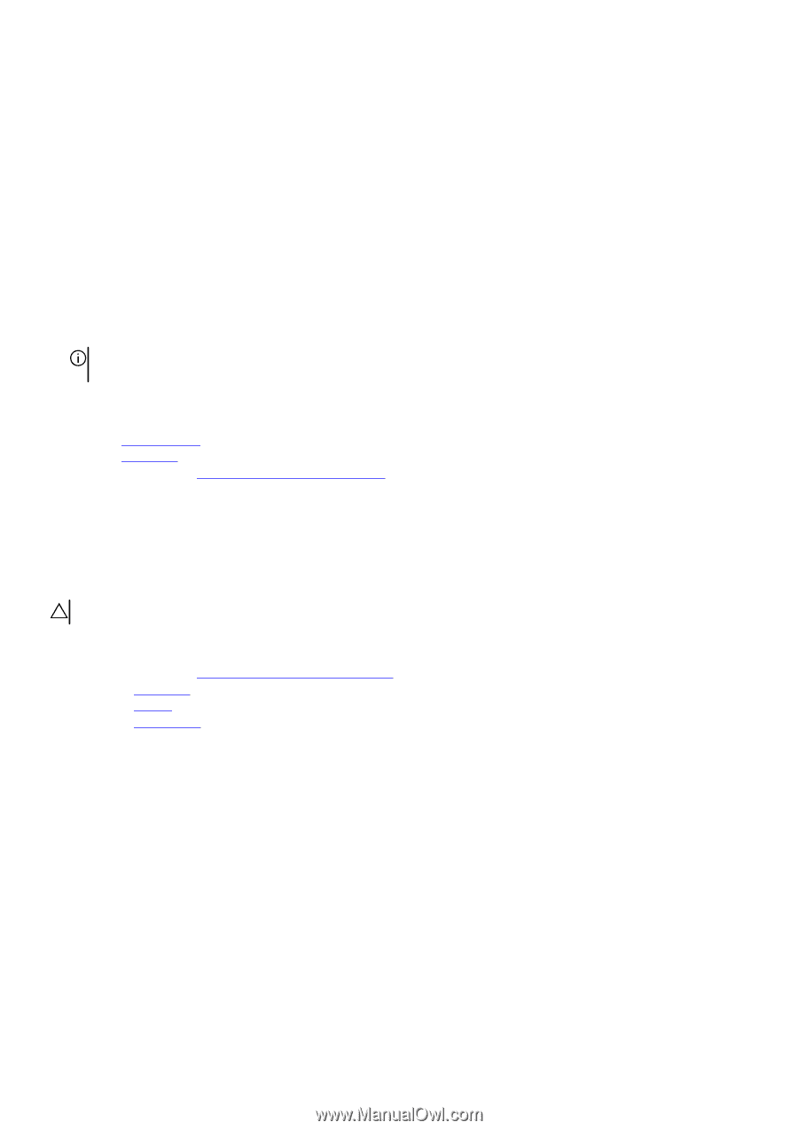
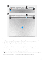
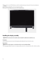
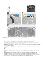
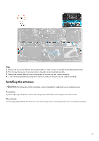
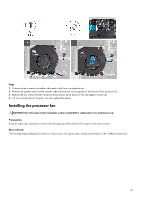
10. Replace the screw (M1.6x3) that secures the microSD-card reader to the display-cable holder. 11. Route the display cable through the opening on the rear side of the palm-rest and keyboard assembly. 12. Rotate the display-cable holder to 180 degrees so that the microSD card-reader aligns with the microSD-card reader slot on the palm-rest and keyboard assembly. 13. Place the display-cable holder on the slot of the palm-rest and keyboard assembly. 14. Replace the four screws (M1.6x3) that secure the display-cable holder to the palm-rest and keyboard assembly. 15. Turn the computer over. 16. Slide the microSD card-reader cable onto the connector on the micorSD-card reader board and close the latch to secure the cable. 17. Align the screw holes on the display assembly with the screw holes on the left and right display hinge on the bottom side of the palm-rest and keyboard assembly. 18. Replace the four screws (M2.5x4) that secure the left and right display hinge to the bottom side of the palm-rest and keyboard assembly. 19. Slide the display cable onto the connector on the system board. 20.Replace the two screws (M2x2.5) that secures the display-cable bracket to the palm-rest and keyboard assembly. NOTE: Check to ensure that the display cable is routed and installed correctly with the display cable holder. If the display cable is visible between the gaps of the display assembly, the installation is incorrect. Next steps 1. Install the rear I/O-cover. 2. Install the base cover. 3. Follow the procedure in After working inside your computer. Antennas Removing the antennas CAUTION: The information in this removal section is intended for authorized service technicians only. Prerequisites 1. Follow the procedure in Before working inside your computer. 2. Remove the base cover. 3. Remove the battery. 4. Remove the wireless card. About this task The following images indicate the location of the antennas and provide a visual representation of the removal procedure. 76
-
 1
1 -
2
-
3
-
4
-
5
-
6
-
7
-
8
-
9
-
10
-
11
-
12
-
13
-
14
-
15
-
16
-
17
-
18
-
19
-
20
-
21
-
22
-
23
-
24
-
25
-
26
-
27
-
28
-
29
-
30
-
31
-
32
-
33
-
34
-
35
-
36
-
37
-
38
-
39
-
40
-
41
-
42
-
43
-
44
-
45
-
46
-
47
-
48
-
49
-
50
-
51
-
52
-
53
-
54
-
55
-
56
-
57
-
58
-
59
-
60
-
61
-
62
-
63
-
64
-
65
-
66
-
67
-
68
-
69
-
70
-
 71
71 -
 72
72 -
 73
73 -
 74
74 -
 75
75 -
 76
76 -
 77
77 -
 78
78 -
 79
79 -
 80
80 -
 81
81 -
82
-
83
-
84
-
85
-
86
-
87
-
88
-
89
-
90
-
91
-
92
-
93
-
94
-
95
-
96
-
97
-
98
-
99
-
100
-
101
-
102
-
103
-
104
-
105
-
106
-
107
-
108
-
109
-
110
-
111
-
112
-
113
-
114
-
115
-
116
-
117
-
118
-
119
-
120
-
121
-
122
-
123
-
124
-
125
-
126
-
127
-
128
-
129
-
130
-
131
-
132
-
133
 |
 |