Dell Force10 C300 Quick Start Guide - Page 10
Attach a Ground Cable to the C150/300 DC Chassis
 |
View all Dell Force10 C300 manuals
Add to My Manuals
Save this manual to your list of manuals |
Page 10 highlights
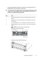
Attach a Ground Cable to the C150/300 DC Chassis WARNING: You must complete the ground connection before proceeding with any DC PEM connection. The AC power cord is the primary ground connection for C-Series AC chassis. This procedure applies to the DC powered chassis only. You must provide your own cables to connect to a remote power source (a circuit breaker panel, for example) in your equipment rack or facility. Cables must be sized to meet the following criteria: • Rated for 60A service to allow for a fully loaded C150 system per NEC in the United States or internationally, per local safety codes. • Limit voltage drop across the cable length to 0.5V or less. NOTE: Apply a coat of anti-oxidant paste to unplated metal contact surfaces before you make the cable connections. File unplated connectors, braided straps, and bus bars to a shiny finish. It is not necessary to file and coat tinned, solder plated, or silver-plated connectors or other plated connection surfaces, such as those on the PEM studs. Step Task 1 Locate the chassis ground connector stud on the PEM front panel. It is the single stud below the safety cover. 2 Remove the nut and washer from the ground stud. 3 Apply a coat of anti-oxidant paste to the connector stud, if required. 4 Install the grounding cable. This cable is typically green or green and yellow. NOTE: Termination points require UL-listed 1-hole lug with a 1/4-inch hole. 5 Replace the washer and nut on the stud. 6 Secure the nut with a nut driver or torque wrench (not to exceed 4 ft/lbs). 7 Connect the opposite end of the grounding cable to the appropriate nearest grounding. 8 Installing the Hardware
-
 1
1 -
2
-
3
-
4
-
 5
5 -
 6
6 -
 7
7 -
 8
8 -
 9
9 -
 10
10 -
 11
11 -
 12
12 -
 13
13 -
 14
14 -
 15
15 -
16
-
17
-
18
-
19
-
20
-
21
-
22
-
23
-
24
-
25
-
26
-
27
-
28
-
29
-
30
-
31
-
32
 |
 |