Dell Force10 C300 Quick Start Guide - Page 14
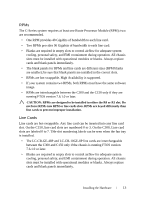
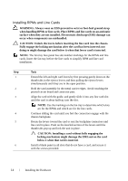
Installing RPMs and Line Cards, The C150 system accommodates four Line Cards and two Route Processor
 |
View all Dell Force10 C300 manuals
Add to My Manuals
Save this manual to your list of manuals |
Page 14 highlights
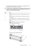
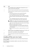
Step Task 5 Secure the PEM in place by tightening the retaining latch on each module so that the arrow points down 6 Remove the outer nuts and washers from each of the remaining studs. 7 Connect the -48 VDC and Return cables from each PEM to the remote power sources. a Verify that the remote power source is in the OFF position. b Locate the appropriate studs on the PEM front panel. - The two right-handed studs (furthest from the GND) are the return (+48V DC) connection. The cable attached to these studs is typically red. - The two left-handed studs (closest to GND) are the -48 V DC connection. The cable attached to these studs is typically black. NOTE: Power cables must be terminated only with a UL-listed 2hole lug to accommodate 1/4-inch studs with 3/4-inch spacing. c Apply a coat of anti-oxidant paste to the connector studs, if required. d Replace the washers and nuts on the studs. e Route the terminated cables out toward the rack rail. Cables will route down toward the floor. You can then route them as best suits your environment. f Secure the nuts with a nut driver or torque wrench (not to exceed 4 ft/lbs). 8 Replace the safety cover and tighten the captive screw. The safety cover can be rotated to accommodate system configurations. 9 Turn the Over-Current Protector to the ON position. 10 Turn the remote power source (the circuit breaker panel) to the ON position. Installing RPMs and Line Cards The C150 system accommodates four Line Cards and two Route Processor Modules (RPMs). The C300 System accommodates eight line cards and two Route Processor Modules (RPMs). 12 Installing the Hardware
-
 1
1 -
2
-
3
-
4
-
5
-
6
-
7
-
8
-
 9
9 -
 10
10 -
 11
11 -
 12
12 -
 13
13 -
 14
14 -
 15
15 -
 16
16 -
 17
17 -
 18
18 -
 19
19 -
20
-
21
-
22
-
23
-
24
-
25
-
26
-
27
-
28
-
29
-
30
-
31
-
32
 |
 |
