Dell Force10 MXL Blade Getting Started Guide - Page 25
Assembling a Switch Stack
 |
View all Dell Force10 MXL Blade manuals
Add to My Manuals
Save this manual to your list of manuals |
Page 25 highlights
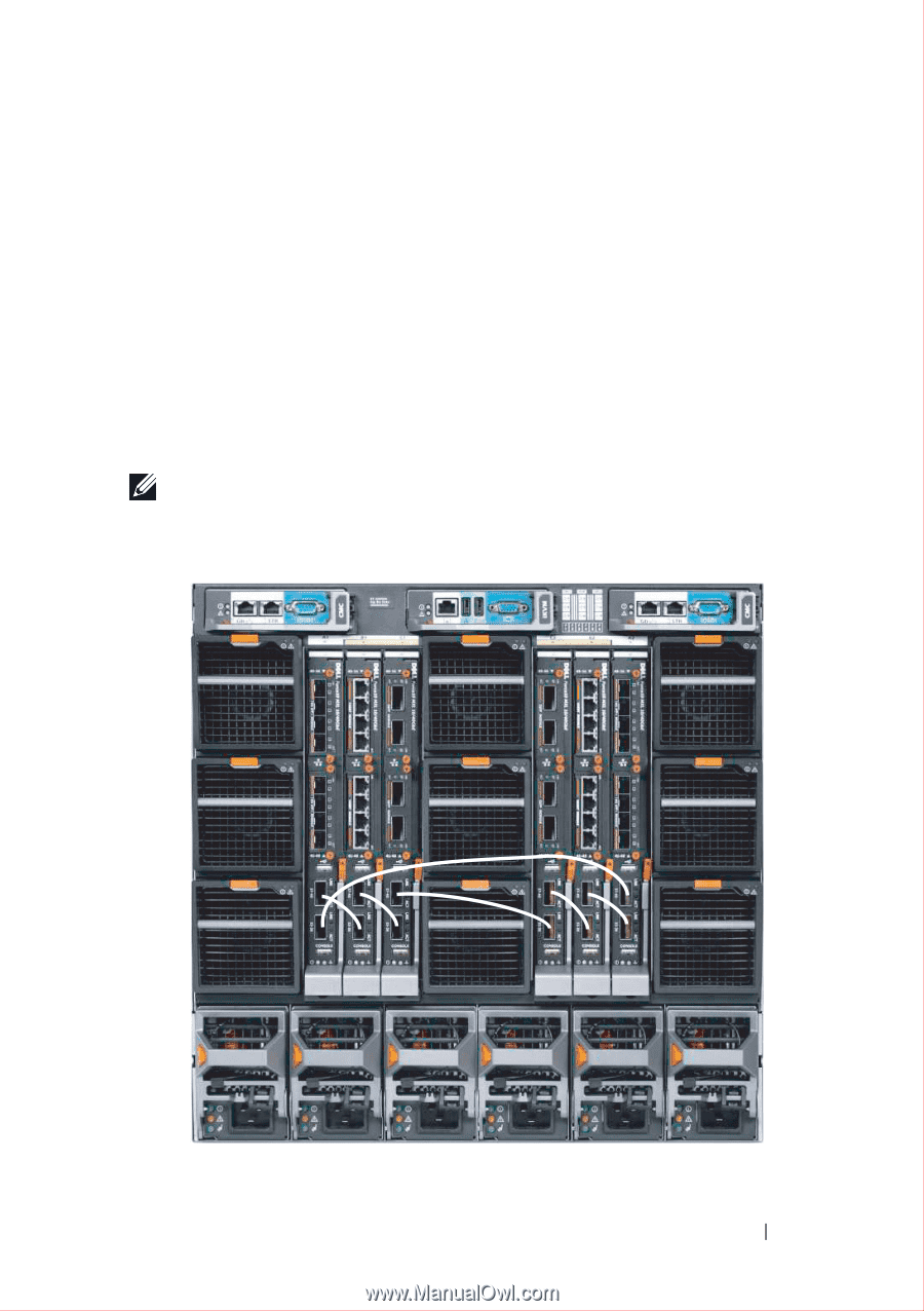
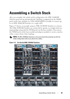
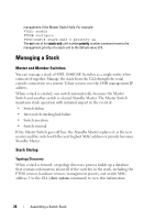
Assembling a Switch Stack After you complete the initial switch configuration, the MXL 10/40GbE Switch is powered up and operational. Stacking is supported on the 40GbE ports on the base module or a 2-Port 40GbE QSFP+ module to connect up to six MXL 10/40GbE Switches in a single stack. Figure 1-9 shows an example using six MXL 10/40GbE Switches in a chassis. The MXL 10/40GbE Switches are connected to operate as a single stack in a ring topology using only the 40GbE ports on the base modules. You can use the 40GbE ports on the base module and plug-in modules to create a stack in either a ring or daisy-chain topology. NOTE: All MXL 10/40GbE Switches in the stack should be powered up with the initial configuration before you attach the cables. Figure 1-9. Six Stacked MXL 10/40GbE Switches Assembling a Switch Stack 25
-
 1
1 -
2
-
3
-
4
-
5
-
6
-
7
-
8
-
9
-
10
-
11
-
12
-
13
-
14
-
15
-
16
-
17
-
18
-
19
-
 20
20 -
 21
21 -
 22
22 -
 23
23 -
 24
24 -
 25
25 -
 26
26 -
 27
27 -
 28
28 -
 29
29 -
 30
30 -
31
-
32
-
33
-
34
-
35
-
36
-
37
-
38
 |
 |