Dell Force10 MXL Blade Getting Started Guide - Page 26
Configuring and Bringing Up a Stack
 |
View all Dell Force10 MXL Blade manuals
Add to My Manuals
Save this manual to your list of manuals |
Page 26 highlights
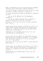
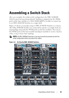
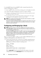
Use only QSFP transceivers and QSFP cables (separately purchased) to connect stacking ports as follows: 1 Insert a QSFP cable in the bottom stacking port on the rightmost switch. 2 Connect the upper stacking port on the next switch to the left. 3 Continue connecting each switch to the next in this way until you reach the leftmost switch in the stack. 4 On the leftmost switch, connect the bottom stacking port to the upper stacking port on the rightmost switch to create a loop. NOTE: The resulting ring topology allows the entire stack to function as a single switch with resilient fail-over capabilities. If you do not connect the leftmost switch to the rightmost switch (Step 4), the stack operates in a daisy-chain topology with less resiliency. Any failure in a non-edge stack unit causes a split stack. Configuring and Bringing Up a Stack NOTE: Although stacking is supported on 40GbE ports on the base module or a 2-Port 40GbE QSFP+ module, this section shows how to configure stacking only on the base-module ports (Figure 1-9). To convert the 40GbE ports on the 2-Port QSFP+ module from their default 4x10GbE mode of operation to 40GbE mode to configure a stack, refer to "FlexIOTM Plug-in Modules" on page 7. After the converting the ports to 40GbE, you do not have to reload the switch because a switch reload is required as part of the stack configuration procedure. After you attach the QSFP+ cables in a stack of MXL 10/40GbE Switches, to configure and bring up the stack, follow these steps: 1 Connect the terminal to the console port on an MXL 10/40GbE Switch. Enter the following commands to access the CLI and configure the two 40GbE ports on the base module for stacking mode: Login: username Password: ***** FTOS> enable FTOS# configure FTOS(conf)# stack-unit 0 stack-group 0 FTOS(conf)# stack-unit 0 stack-group 1 Where stack-unit 0 defines the default stack-unit number in the initial configuration of a switch; stack-group 0 defines the stack group for the 26 Assembling a Switch Stack
-
 1
1 -
2
-
3
-
4
-
5
-
6
-
7
-
8
-
9
-
10
-
11
-
12
-
13
-
14
-
15
-
16
-
17
-
18
-
19
-
20
-
 21
21 -
 22
22 -
 23
23 -
 24
24 -
 25
25 -
 26
26 -
 27
27 -
 28
28 -
 29
29 -
 30
30 -
 31
31 -
32
-
33
-
34
-
35
-
36
-
37
-
38
 |
 |