Dell Inspiron m301z AMD Service Manual - Page 21
Replacing the Display Assembly
 |
View all Dell Inspiron m301z manuals
Add to My Manuals
Save this manual to your list of manuals |
Page 21 highlights
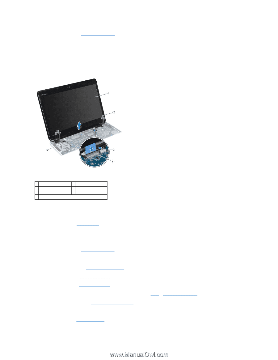
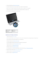
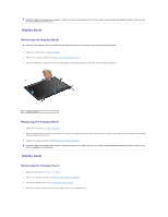
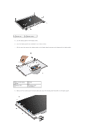
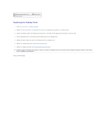
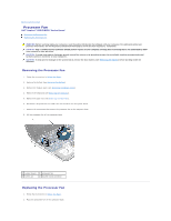
11. Remove the hinge caps (see Removing the Hinge Caps). 12. Disconnect the display cable and the camera cable from their connectors on the system board. 13. Make a note of the routing of the Mini-Card antenna cables and remove the cables from the routing guides. 14. Remove the six screws (three on each side) that secure the display assembly to the computer base. 15. Lift and remove the display assembly off the computer base. 1 display assembly 2 screws (6) 3 camera cable connector 4 display cable connector 5 Mini-Card antenna cables Replacing the Display Assembly 1. Follow the instructions in Before You Begin. 2. Place the display assembly in position and replace the six screws (three on each side) that secure the display assembly to the computer base. 3. Route the Mini-Card antenna cables through the slot on the computer base. 4. Replace the hinge caps (see Replacing the Hinge Caps). 5. Connect the display cable and the camera cable to their connectors on the system board. 6. Replace the Bluetooth card (see Replacing the Bluetooth Card). 7. Replace the palm rest (see Replacing the Palm Rest). 8. Replace the keyboard (see Replacing the Keyboard). 9. Turn the computer over and connect the antenna cables to the Mini- Card(s) (see step 7 of Replacing the Mini-Card(s)). 10. Replace the memory module(s) (see Replacing the Memory Module(s)). 11. Replace the module cover (see Replacing the Module Cover). 12. Replace the battery (see Replacing the Battery).
-
 1
1 -
2
-
3
-
4
-
5
-
6
-
7
-
8
-
9
-
10
-
11
-
12
-
13
-
14
-
15
-
 16
16 -
 17
17 -
 18
18 -
 19
19 -
 20
20 -
 21
21 -
 22
22 -
 23
23 -
 24
24 -
 25
25 -
 26
26 -
27
-
28
-
29
-
30
-
31
-
32
-
33
-
34
-
35
-
36
-
37
-
38
-
39
-
40
-
41
-
42
-
43
-
44
-
45
-
46
-
47
-
48
-
49
-
50
-
51
-
52
 |
 |