Dell Inspiron m301z AMD Service Manual - Page 50
Replacing the System Board
 |
View all Dell Inspiron m301z manuals
Add to My Manuals
Save this manual to your list of manuals |
Page 50 highlights
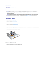
1 screws (4) 2 system board 17. Carefully ease the connectors on the system board out of the slots in the computer, and lift the system board out of the computer. 18. Turn the system board assembly over. 19. Remove the Mini-Card(s) (see Removing the Mini-Card(s)). 20. Remove the processor heat sink assembly (see Removing the Processor Heat Sink Assembly). Replacing the System Board 1. Follow the instructions in Before You Begin. 2. Replace the processor heat sink assembly (see Replacing the Processor Heat Sink Assembly). 3. Replace the Mini-Card(s) (see Replacing the Mini-Card(s)). 4. Turn the system board assembly over. 5. Align the connectors on the system board with the slots on the computer base, and use the alignment posts on the computer base to correctly place the system board. 6. Replace the four screws that secure the system board to the computer base. 7. Connect the coin-cell battery cable, speaker cable, status light board cable, and the AC adapter connector cable to their respective connectors on the system board. 8. Place the left hinge-bracket on the computer base. 9. Replace the screw that secures the left hinge-bracket. 10. Replace the middle cover (see Replacing the Middle Cover). 11. Replace the display assembly (see Replacing the Display Assembly). 12. Follow the instructions from step 6 to step 8 in Replacing the Hard Drive Assembly. 13. Replace the processor fan (see Replacing the Processor Fan). 14. Replace the Bluetooth card (see Replacing the Bluetooth Card). 15. Replace the palm rest (see Replacing the Palm Rest). 16. Replace the keyboard (see Replacing the Keyboard). 17. Turn the computer over and replace the screw that secures the left hinge- bracket to the computer base. 18. Replace the memory module(s) (see Replacing the Memory Module(s)). 19. Replace the module cover (see Replacing the Module Cover). 20. Replace the battery (see Replacing the Battery). CAUTION: Before turning on the computer, replace all screws and ensure that no stray screws remain inside the computer. Failure to do so may result in damage to the computer. 21. Turn on the computer. NOTE: After you have replaced the system board, enter the computer's Service Tag into the BIOS of the replacement system board. 22. Enter the service tag (see Entering the Service Tag in the BIOS).
-
 1
1 -
2
-
3
-
4
-
5
-
6
-
7
-
8
-
9
-
10
-
11
-
12
-
13
-
14
-
15
-
16
-
17
-
18
-
19
-
20
-
21
-
22
-
23
-
24
-
25
-
26
-
27
-
28
-
29
-
30
-
31
-
32
-
33
-
34
-
35
-
36
-
37
-
38
-
39
-
40
-
41
-
42
-
43
-
44
-
 45
45 -
 46
46 -
 47
47 -
 48
48 -
 49
49 -
 50
50 -
 51
51 -
 52
52
 |
 |