Dell Latitude CPi A User Manual - Page 21
Memory Modules, s two metal retaining clips.
 |
View all Dell Latitude CPi A manuals
Add to My Manuals
Save this manual to your list of manuals |
Page 21 highlights
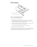
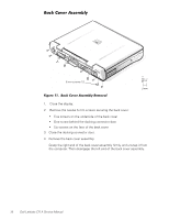
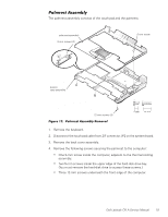
memory module sockets (2) retaining clips (2 per socket) 1. Remove the memory module cover. 2. To avoid possible damage to the memory module from electrostatic discharge (ESD), ground yourself by touching the unpainted metal surface of an I/O connector on the computer's back panel. 3. To release a memory module from its socket, gently push outward on each of the memory module's two metal retaining clips. The memory module rotates upward out of its retaining clips. 4. Lift the memory module out of its socket. You can install memory modules only one way. Do not attempt to force the memory module into the socket. Align the notch near the center of the memory module with the corresponding key in the memory module socket. Dell Latitude CPi A Service Manual 15
-
 1
1 -
2
-
3
-
4
-
5
-
6
-
7
-
8
-
9
-
10
-
11
-
12
-
13
-
14
-
15
-
 16
16 -
 17
17 -
 18
18 -
 19
19 -
 20
20 -
 21
21 -
 22
22 -
 23
23 -
 24
24 -
 25
25 -
 26
26 -
27
-
28
-
29
-
30
-
31
-
32
-
33
-
34
-
35
-
36
-
37
-
38
-
39
-
40
-
41
-
42
-
43
-
44
-
45
-
46
-
47
-
48
-
49
-
50
 |
 |
