Dell Latitude CPi A User Manual - Page 29
Display Assembly Bezel, fingertips between the bezel and the LCD panel, and lift upward on the bezel
 |
View all Dell Latitude CPi A manuals
Add to My Manuals
Save this manual to your list of manuals |
Page 29 highlights
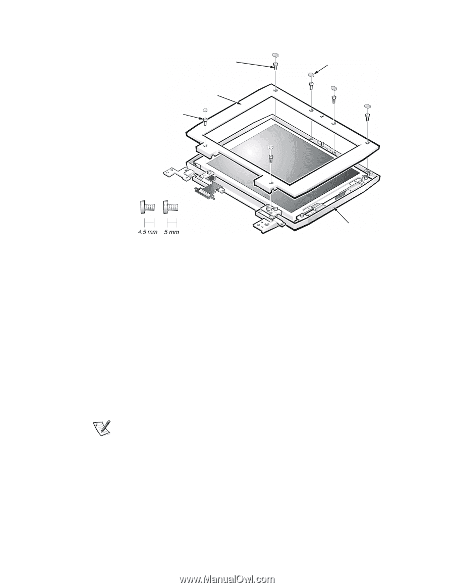
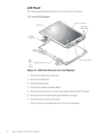
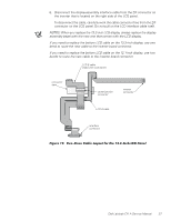
4.5-mm screws (4) display assembly bezel 5-mm screws (2) screw covers (6) display-assembly top cover 1. Use a scribe to carefully pry the screw covers out of the six screw holes in the bezel. 2. Remove the six screws from the bezel. The four upper screws are 4.5-mm screws, while the two lower screws are 5-mm in length. 3. Separate the bezel from the display-assembly top cover. The bezel is secured by snaps around all four of its edges. Insert your fingertips between the bezel and the LCD panel, and lift upward on the bezel to release the hidden snaps. Avoid pressing on the surface of the LCD panel. NOTE: On a 13.3-inch display, you must remove the LCD panel before you can remove the display assembly latch. 1. Remove the display assembly bezel. 2. Remove the display assembly latch by unsnapping the latch and captive spring from the inside of the display assembly top-cover assembly. Dell Latitude CPi A Service Manual 23
-
 1
1 -
2
-
3
-
4
-
5
-
6
-
7
-
8
-
9
-
10
-
11
-
12
-
13
-
14
-
15
-
16
-
17
-
18
-
19
-
20
-
21
-
22
-
23
-
 24
24 -
 25
25 -
 26
26 -
 27
27 -
 28
28 -
 29
29 -
 30
30 -
 31
31 -
 32
32 -
 33
33 -
 34
34 -
35
-
36
-
37
-
38
-
39
-
40
-
41
-
42
-
43
-
44
-
45
-
46
-
47
-
48
-
49
-
50
 |
 |