Dell Latitude CPi A User Manual - Page 40
Speakers, to the speaker wires
 |
View all Dell Latitude CPi A manuals
Add to My Manuals
Save this manual to your list of manuals |
Page 40 highlights
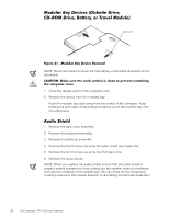
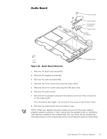
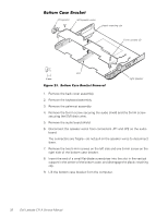
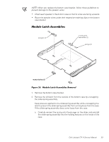
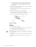
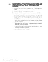
b. Ensure that the plunger is inserted in its respective hole, that the side of the slider with the two bumps is facing the rear of the case, and that the surface with the wear ribs is facing the bottom of the case (see Figure 25). 3. Snap in the new latch from the bottom of the base, making certain its snap features are fully engaged in the slider. 4. Ensure that the newly installed latch moves smoothly and freely when pushed and released. 5. Repeat steps 1 through 4 for the latch on the right side. 6. On the base plastic, find the molded label "P.N. ASSY 89501"; then use a permanent marker to write "A01" to the right of "89501." This revision mark indicates that the latch rework is complete. bump side wear ribs (2) 1. Remove the bottom case bracket. 2. If you are replacing the left speaker, carefully remove the speaker wires from the retaining clips along the bracket's edges. 3. Remove the speaker from the bottom case bracket. NOTE: When you replace the speaker, follow these guidelines to prevent damage to the speaker wires: Orient the speaker in the bottom case so that the speaker wires are facing upwards. Route the speaker wires under their retaining clips on the bottom case bracket. 34 Dell Latitude CPi A Service Manual
-
 1
1 -
2
-
3
-
4
-
5
-
6
-
7
-
8
-
9
-
10
-
11
-
12
-
13
-
14
-
15
-
16
-
17
-
18
-
19
-
20
-
21
-
22
-
23
-
24
-
25
-
26
-
27
-
28
-
29
-
30
-
31
-
32
-
33
-
34
-
 35
35 -
 36
36 -
 37
37 -
 38
38 -
 39
39 -
 40
40 -
 41
41 -
 42
42 -
 43
43 -
 44
44 -
 45
45 -
46
-
47
-
48
-
49
-
50
 |
 |
