Dell Latitude CPi A User Manual - Page 9
Screw Identification and Tightening, s label. A graphic for that length screw is also included - latitude cpi a
 |
View all Dell Latitude CPi A manuals
Add to My Manuals
Save this manual to your list of manuals |
Page 9 highlights
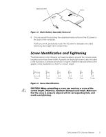
9. Ground yourself by touching the unpainted metal surface of the I/O panel on the back of the computer. While you work, periodically touch the I/O panel to dissipate any static electricity that might harm components. The illustrations in the following removal procedures provide the correct screw length as part of the screw's label. A graphic for that length screw is also included in the illustration. Examples are shown in Figure 3. Match the actual screw to the graphic in the illustration to check for correct length. Dell Latitude CPi A Service Manual 3
-
 1
1 -
2
-
3
-
 4
4 -
 5
5 -
 6
6 -
 7
7 -
 8
8 -
 9
9 -
 10
10 -
 11
11 -
 12
12 -
 13
13 -
 14
14 -
15
-
16
-
17
-
18
-
19
-
20
-
21
-
22
-
23
-
24
-
25
-
26
-
27
-
28
-
29
-
30
-
31
-
32
-
33
-
34
-
35
-
36
-
37
-
38
-
39
-
40
-
41
-
42
-
43
-
44
-
45
-
46
-
47
-
48
-
49
-
50
 |
 |

Dell Latitude CPi A Service Manual
3
±²³´µ¶·Â¹··ÃÁ²À·ÄÁ¾¾¶µÅ·ÆÇǶ¼ÈÉŷʶ¼»ËÁÉ
9.
Ground yourself by touching the unpainted metal surface of the I/O panel on
the back of the computer.
While you work, periodically touch the I/O panel to dissipate any static
electricity that might harm components.
ÍÅ»²ÎµË´²Â¼¸Ï¸Å³¼¸¾Âµ³Â´µ¶¸Ä·¼²Â¸ÂÄ
The illustrations in the following removal procedures provide the correct screw
length as part of the screw
’
s label. A graphic for that length screw is also included
in the illustration. Examples are shown in Figure 3. Match the actual screw to the
graphic in the illustration to check for correct length.
±²³´µ¶·Ì¹··Íε¶Ï·°!¶À¾²"²ÎÁ¾²»À
±²³´µ¶·¸ °Á¿º ¿¹ºÀ¾½ÅŹºÇ ½ À¼Â¿È% ÊÄË ÆËÀ¾ ËÀ¿ ½ À¼Â¿È ÄÉ ¾Á¿
¼Ä¿¼¾ Å¿ºÇ¾ÁÎ ¶¾Á¿ÂȹÀ¿% Á½Â»È½Â¿ »½Æ½Ç¿ ¼ÄËÅ» ¿ÀËžΠ#½$¿ ÀË¿
¾Á½¾ ¾Á¿ À¼Â¿È ¹À ÃÂÄÿÂÅÊ ½Å¹Çº¿» ȹ¾Á ¹¾À ¼Ä¿ÀÃĺ»¹ºÇ ÁÄÅ¿% ½º»
½ÌĹ» Ä̿¾¹ÇÁ¾¿º¹ºÇÎ
±²³³´µ¶·±²¶·¸²³¹º
±²³³´µ