Dell Latitude CPi A User Manual - Page 28
Close the display, being careful not to damage the display-assembly interface
 |
View all Dell Latitude CPi A manuals
Add to My Manuals
Save this manual to your list of manuals |
Page 28 highlights
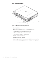
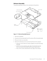
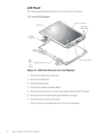
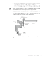
1. Remove the back cover assembly. 2. Remove the keyboard. 3. Remove the palmrest assembly. 4. Remove the two black 5-mm interface-cable grounding screws and the interface cable bracket. 5. Disconnect the display-assembly interface cable from connector JP1 on the system board. Grasp the grounding tabs and pull the connector straight up from the system board. 6. Close the display, being careful not to damage the display-assembly interface cable. 7. Remove the four silver 5-mm screws securing each of the two hinge brackets to the bottom case assembly. 8. Lift the display assembly from the bottom case assembly. NOTE: When you reinstall the display assembly, install the four screws securing the hinges at the locations marked by arrows on the face of each hinge. 22 Dell Latitude CPi A Service Manual
-
 1
1 -
2
-
3
-
4
-
5
-
6
-
7
-
8
-
9
-
10
-
11
-
12
-
13
-
14
-
15
-
16
-
17
-
18
-
19
-
20
-
21
-
22
-
 23
23 -
 24
24 -
 25
25 -
 26
26 -
 27
27 -
 28
28 -
 29
29 -
 30
30 -
 31
31 -
 32
32 -
 33
33 -
34
-
35
-
36
-
37
-
38
-
39
-
40
-
41
-
42
-
43
-
44
-
45
-
46
-
47
-
48
-
49
-
50
 |
 |
