Dell Latitude CPi A User Manual - Page 34
LCD Display Hinge, Display-Assembly Top Cover, Bottom Case Assembly, Bottom case bracket
 |
View all Dell Latitude CPi A manuals
Add to My Manuals
Save this manual to your list of manuals |
Page 34 highlights
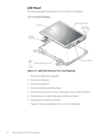
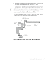
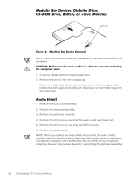
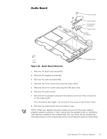
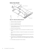
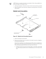
1. Remove the LCD display assembly from the computer. 2. Remove the display assembly bezel. 3. Remove the four silver 5-mm screws securing the two hinge brackets to the display-assembly top cover. NOTE: To aid in reinstalling the hinges and display assembly, the right and left hinges are marked by an "R" and an "L," respectively. Install the four screws securing the hinges at the locations marked by arrows on the face of each hinge. 1. Remove the display assembly. 2. Remove the display assembly bezel. 3. Remove the LCD panel. 4. Remove the display assembly latch. 5. Remove the left and right hinges. 6. Remove the display-assembly interface cable. The bottom case assembly consists of the following field-replaceable components: Modular bay device (diskette drive assembly, CD-ROM drive assembly, or travel module) Back cover assembly Audio shield Audio board Bottom case bracket Module latch assemblies Speakers System board assembly Thermal cooling assembly Air flow duct Exhaust fan Infrared (I/R) board Reserve battery 28 Dell Latitude CPi A Service Manual
-
 1
1 -
2
-
3
-
4
-
5
-
6
-
7
-
8
-
9
-
10
-
11
-
12
-
13
-
14
-
15
-
16
-
17
-
18
-
19
-
20
-
21
-
22
-
23
-
24
-
25
-
26
-
27
-
28
-
 29
29 -
 30
30 -
 31
31 -
 32
32 -
 33
33 -
 34
34 -
 35
35 -
 36
36 -
 37
37 -
 38
38 -
 39
39 -
40
-
41
-
42
-
43
-
44
-
45
-
46
-
47
-
48
-
49
-
50
 |
 |