Dell Latitude E6530 Owners Manual - Page 35
Installing the Power LED Board, Removing the Input/Output (I/O) Board - display
 |
View all Dell Latitude E6530 manuals
Add to My Manuals
Save this manual to your list of manuals |
Page 35 highlights
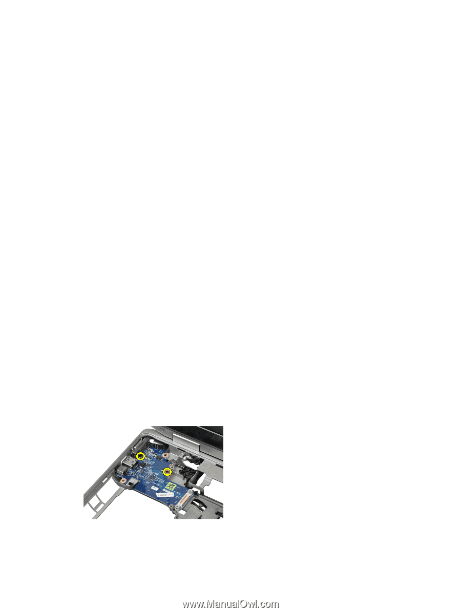
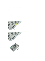
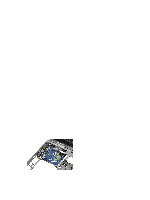
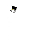
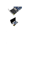
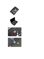
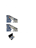
Installing the Power LED Board 1. Place the power LED board in its compartment in the display assembly. 2. Tighten the screw to secure the LED board to the display assembly. 3. Connect the power LED board cable to the display assembly. 4. Install: a) display panel b) display bezel c) display assembly d) keyboard e) keyboard trim f) bluetooth module g) hard drive h) base cover i) battery 5. Follow the procedures in After Working Inside Your Computer. Removing the Input/Output (I/O) Board 1. Follow the procedures in Before Working Inside Your Computer. 2. Remove: a) battery b) base cover c) hard drive d) optical drive e) bluetooth card f) keyboard trim g) keyboard h) display assembly i) palmrest j) media board (available in E6430/E6430 ATG only) k) ExpressCard cage l) system board 3. Remove the screw that secures the I/O board to the computer. 35
-
 1
1 -
2
-
3
-
4
-
5
-
6
-
7
-
8
-
9
-
10
-
11
-
12
-
13
-
14
-
15
-
16
-
17
-
18
-
19
-
20
-
21
-
22
-
23
-
24
-
25
-
26
-
27
-
28
-
29
-
 30
30 -
 31
31 -
 32
32 -
 33
33 -
 34
34 -
 35
35 -
 36
36 -
 37
37 -
 38
38 -
 39
39 -
 40
40 -
41
-
42
-
43
-
44
-
45
-
46
-
47
-
48
-
49
-
50
-
51
-
52
-
53
-
54
-
55
-
56
-
57
-
58
-
59
-
60
-
61
-
62
-
63
-
64
-
65
-
66
-
67
-
68
-
69
-
70
-
71
-
72
-
73
-
74
-
75
-
76
-
77
-
78
-
79
-
80
-
81
-
82
-
83
-
84
-
85
-
86
-
87
 |
 |