Dell Latitude E6530 Owners Manual - Page 60
Installing the LVDS and Camera Cable
 |
View all Dell Latitude E6530 manuals
Add to My Manuals
Save this manual to your list of manuals |
Page 60 highlights
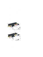
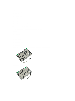
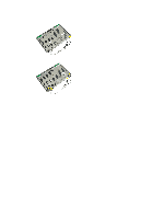
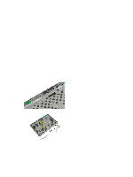
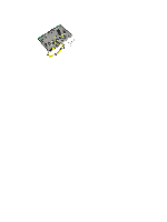
5. Remove the LVDS and camera cable from the display assembly. Installing the LVDS and Camera Cable 1. Route the LVDS and camera cable on the display assembly. 2. Fix the adhesive the tape to secure the cable. 3. Connect the LVDS and camera cable to the camera. 4. Install: a) display hinges b) display panel c) display bezel d) display assembly e) keyboard f) keyboard trim g) bluetooth card h) hard drive i) base cover j) battery 5. Follow the procedures in After Working Inside Your Computer. 60
-
 1
1 -
2
-
3
-
4
-
5
-
6
-
7
-
8
-
9
-
10
-
11
-
12
-
13
-
14
-
15
-
16
-
17
-
18
-
19
-
20
-
21
-
22
-
23
-
24
-
25
-
26
-
27
-
28
-
29
-
30
-
31
-
32
-
33
-
34
-
35
-
36
-
37
-
38
-
39
-
40
-
41
-
42
-
43
-
44
-
45
-
46
-
47
-
48
-
49
-
50
-
51
-
52
-
53
-
54
-
 55
55 -
 56
56 -
 57
57 -
 58
58 -
 59
59 -
 60
60 -
 61
61 -
 62
62 -
 63
63 -
 64
64 -
 65
65 -
66
-
67
-
68
-
69
-
70
-
71
-
72
-
73
-
74
-
75
-
76
-
77
-
78
-
79
-
80
-
81
-
82
-
83
-
84
-
85
-
86
-
87
 |
 |
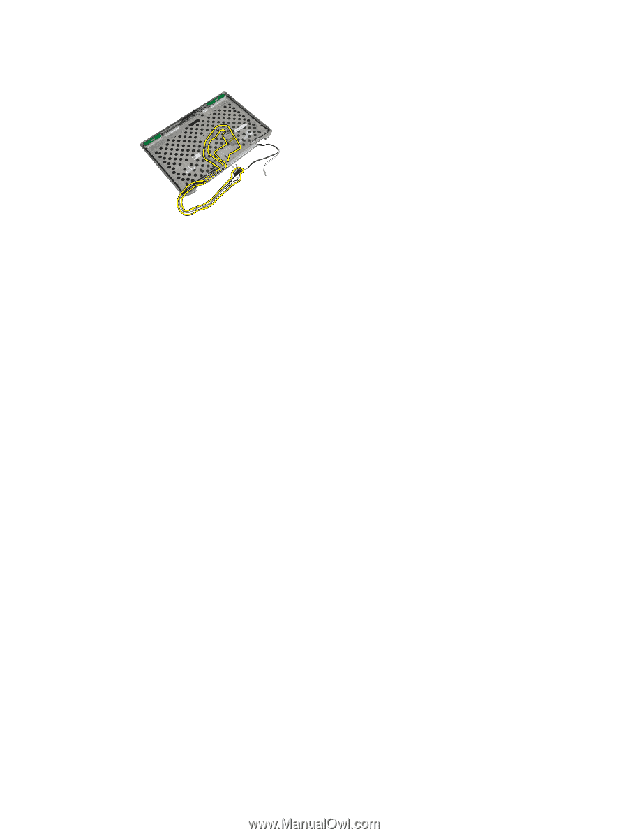
5.
Remove the LVDS and camera cable from the display assembly.
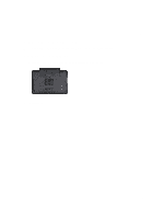
Installing the LVDS and Camera Cable
1.
Route the LVDS and camera cable on the display assembly.
2.
Fix the adhesive the tape to secure the cable.
3.
Connect the LVDS and camera cable to the camera.
4.
Install:
a)
display hinges
b)
display panel
c)
display bezel
d)
display assembly
e)
keyboard
f)
keyboard trim
g)
bluetooth card
h)
hard drive
i)
base cover
j)
battery
5.
Follow the procedures in
After Working Inside Your Computer
.
60