Dell Latitude E6530 Owners Manual - Page 41
Installing the WiFi-Switch Board, Removing the System Board - will not connect to wifi
 |
View all Dell Latitude E6530 manuals
Add to My Manuals
Save this manual to your list of manuals |
Page 41 highlights
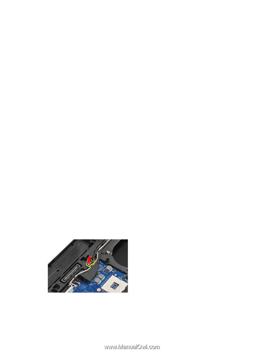
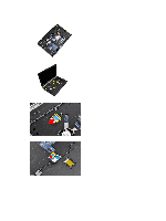
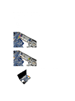
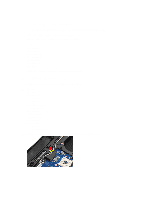
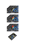
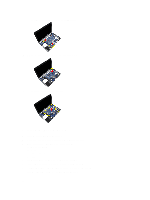
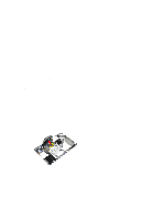
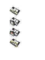
Installing the WiFi-Switch Board 1. Fix the adhesive tape on the back of the WiFi-switch board and place the board in its slot. 2. Tighten the screw to secure the WiFi-switch board. 3. Connect the WiFi-switch board cable to the system board. 4. Install: a) palmrest b) keyboard c) keyboard trim d) optical drive e) hard drive f) base cover g) battery 5. Follow the procedures in After Working Inside Your Computer. Removing the System Board 1. Follow the procedures in Before Working Inside Your Computer. 2. Remove: a) battery b) base cover c) hard drive d) optical drive e) bluetooth card f) keyboard trim g) keyboard h) WLAN card i) modem card j) heat sink k) processor l) palmrest m) ExpressCard cage 3. Disconnect the power-connector cable from the bottom side of the system board. 41
-
 1
1 -
2
-
3
-
4
-
5
-
6
-
7
-
8
-
9
-
10
-
11
-
12
-
13
-
14
-
15
-
16
-
17
-
18
-
19
-
20
-
21
-
22
-
23
-
24
-
25
-
26
-
27
-
28
-
29
-
30
-
31
-
32
-
33
-
34
-
35
-
 36
36 -
 37
37 -
 38
38 -
 39
39 -
 40
40 -
 41
41 -
 42
42 -
 43
43 -
 44
44 -
 45
45 -
 46
46 -
47
-
48
-
49
-
50
-
51
-
52
-
53
-
54
-
55
-
56
-
57
-
58
-
59
-
60
-
61
-
62
-
63
-
64
-
65
-
66
-
67
-
68
-
69
-
70
-
71
-
72
-
73
-
74
-
75
-
76
-
77
-
78
-
79
-
80
-
81
-
82
-
83
-
84
-
85
-
86
-
87
 |
 |