Dell Latitude E6530 Owners Manual - Page 49
Installing the Display Assembly, Connect the following cables to the computer
 |
View all Dell Latitude E6530 manuals
Add to My Manuals
Save this manual to your list of manuals |
Page 49 highlights
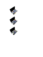
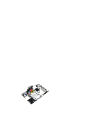
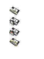
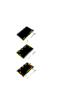
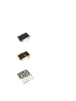
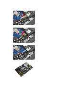
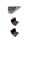
8. Remove the screws to release the display assembly on both sides. 9. Lift the display assembly and pull the LVDS and the antenna cables through the opening of the computer. 10. Remove the display assembly from the computer. Installing the Display Assembly 1. Place the display assembly onto the computer. 2. Insert the LVDS and wireless antenna cables through the holes on the base chassis and connect them. 3. Tighten the screws on both corners to secure the display assembly. 4. Route the antenna and the LVDS cables through the routing channel. 5. Connect the following cables to the computer: a) LVDS b) camera 6. Connect the LVDS support bracket in its position on the computer. 7. Tighten the screw to secure the support bracket to the computer. 49
-
 1
1 -
2
-
3
-
4
-
5
-
6
-
7
-
8
-
9
-
10
-
11
-
12
-
13
-
14
-
15
-
16
-
17
-
18
-
19
-
20
-
21
-
22
-
23
-
24
-
25
-
26
-
27
-
28
-
29
-
30
-
31
-
32
-
33
-
34
-
35
-
36
-
37
-
38
-
39
-
40
-
41
-
42
-
43
-
 44
44 -
 45
45 -
 46
46 -
 47
47 -
 48
48 -
 49
49 -
 50
50 -
 51
51 -
 52
52 -
 53
53 -
 54
54 -
55
-
56
-
57
-
58
-
59
-
60
-
61
-
62
-
63
-
64
-
65
-
66
-
67
-
68
-
69
-
70
-
71
-
72
-
73
-
74
-
75
-
76
-
77
-
78
-
79
-
80
-
81
-
82
-
83
-
84
-
85
-
86
-
87
 |
 |
