Dell OptiPlex 360 Setup and Quick Reference Guide - Page 34
PCI Express x16 - motherboard
 |
View all Dell OptiPlex 360 manuals
Add to My Manuals
Save this manual to your list of manuals |
Page 34 highlights
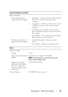
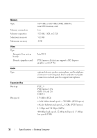
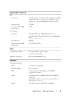
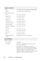
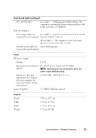
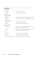
Connectors (continued) PS/2 Parallel System board connectors: SATA Floppy drive Processor fan Chassis fan PCI Express x16 Front panel control Front panel USB Front panel audio HDA header Processor Memory Power 12 V Power LAN on motherboard (LOM) Controls and Lights Front of computer: Power button Power light one, through PS/2 serial expansion card (low profile) one 25-pin connector (bidirectional) three 7-pin connectors one 34-pin connector one 4-pin connector one 3-pin connector one 164-pin connector one 10-pin connector one 10-pin connectors one 10-pin connector one 775-pin connector four 240-pin connectors one 4-pin connector one 24-pin connector through RJ-45 connector on back panel push button green light - Blinking green in sleep state; solid green for power-on state amber light - The blinking amber indicates a problem with the system board. A solid amber light when the computer does not start indicates that the system board cannot start initialization. This indication could be a system board or a power supply problem (see "Power Problems" on page 37). 34 Specifications - Desktop Computer
-
 1
1 -
2
-
3
-
4
-
5
-
6
-
7
-
8
-
9
-
10
-
11
-
12
-
13
-
14
-
15
-
16
-
17
-
18
-
19
-
20
-
21
-
22
-
23
-
24
-
25
-
26
-
27
-
28
-
 29
29 -
 30
30 -
 31
31 -
 32
32 -
 33
33 -
 34
34 -
 35
35 -
 36
36 -
 37
37 -
 38
38 -
 39
39 -
40
-
41
-
42
-
43
-
44
-
45
-
46
-
47
-
48
-
49
-
50
-
51
-
52
-
53
-
54
-
55
-
56
-
57
-
58
-
59
-
60
-
61
-
62
 |
 |