Dell OptiPlex 5090 Tower Service Manual
Dell OptiPlex 5090 Tower Manual
 |
View all Dell OptiPlex 5090 Tower manuals
Add to My Manuals
Save this manual to your list of manuals |
Dell OptiPlex 5090 Tower manual content summary:
- Dell OptiPlex 5090 Tower | Service Manual - Page 1
OptiPlex 5090 Tower Service Manual Regulatory Model: D29M Regulatory Type: D29M003 December 2021 Rev. A03 - Dell OptiPlex 5090 Tower | Service Manual - Page 2
of data and tells you how to avoid the problem. WARNING: A WARNING indicates a potential for property damage, personal injury, or death. © 2021 Dell Inc. or its subsidiaries. All rights reserved. Dell, EMC, and other trademarks are trademarks of Dell Inc. or its subsidiaries. Other trademarks may be - Dell OptiPlex 5090 Tower | Service Manual - Page 3
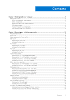
Contents Chapter 1: Working inside your computer 6 Safety instructions...6 Before working inside your computer...6 Safety precautions...7 Electrostatic discharge-ESD protection...7 ESD field service kit ...8 Transporting sensitive components...9 After working inside your computer...9 Chapter 2: - Dell OptiPlex 5090 Tower | Service Manual - Page 4
Processor...34 Removing the processor...34 Installing the processor...35 Expansion card...37 Removing the graphics card...37 Installing the graphics card...38 Graphical processing unit...39 Removing the powered GPU...39 Installing the powered GPU...40 Coin-cell battery...41 Removing the coin-cell - Dell OptiPlex 5090 Tower | Service Manual - Page 5
password...81 Deleting or changing an existing system setup password 81 Chapter 5: Troubleshooting...83 SupportAssist diagnostics...83 Diagnostic LED behavior...83 Recovering the operating system...84 power (perform hard reset)...86 Chapter 6: Getting help and contacting Dell 87 Contents 5 - Dell OptiPlex 5090 Tower | Service Manual - Page 6
and the contacts. CAUTION: You should only perform troubleshooting and repairs as authorized or directed by the Dell technical assistance team. Damage due to servicing that is not authorized by Dell is not covered by your warranty. See the safety instructions that is shipped with the product or at - Dell OptiPlex 5090 Tower | Service Manual - Page 7
performing any disassembly instructions. Observe the Use an ESD field service kit when working inside any desktop to avoid electrostatic not be obvious, such as intermittent problems or a shortened product life span. Dell products, the sensitivity to static damage is now higher than in previous Dell - Dell OptiPlex 5090 Tower | Service Manual - Page 8
and troubleshoot is the hardware is known as bonding. Use only Field Service kits with a wrist strap, mat, and bonding wire desktop or portable environment. Servers are typically installed in a rack within a data center; desktops to be returned to Dell, it is critical to place these parts - Dell OptiPlex 5090 Tower | Service Manual - Page 9
wrist strap and protective anti-static mat at all times when servicing Dell products. In addition, it is critical that technicians keep sensitive parts separate from all insulator parts while performing service and that they use anti-static bags for transporting sensitive components. Transporting - Dell OptiPlex 5090 Tower | Service Manual - Page 10
2 Removing and installing components NOTE: The images in this document may differ from your computer depending on the configuration you ordered. Recommended tools The procedures in this document require the following tools: ● Phillips #0 screwdriver ● Phillips #1 screwdriver ● Flat headed - Dell OptiPlex 5090 Tower | Service Manual - Page 11
Major components of your system 1. Side cover Removing and installing components 11 - Dell OptiPlex 5090 Tower | Service Manual - Page 12
9. Speaker 10. Front bezel 11. Chassis 12. System board 13. Powered Graphical processing unit 14. M.2 WLAN 15. Power Supply Unit NOTE: Dell provides a list of components and their part numbers for the original system configuration purchased. These parts are available according to warranty coverages - Dell OptiPlex 5090 Tower | Service Manual - Page 13
Steps 1. Loosen the two thumbscrews (#6-32) that secure the side cover to the computer. 2. Slide the side cover towards the rear of the computer and lift the cover away from the computer. Installing the side cover Prerequisites If you are replacing a component, remove the existing component before - Dell OptiPlex 5090 Tower | Service Manual - Page 14
Steps 1. Locate the side cover slot on your computer. 2. Align the tabs on the side cover with the slots on the chassis. 3. Slide the side cover towards the front of the computer to install it. 4. Tighten the two thumbscrews (#6-32) to secure the side cover to the computer. Next steps 1. Follow the - Dell OptiPlex 5090 Tower | Service Manual - Page 15
Front bezel Removing the front bezel Prerequisites 1. Follow the procedure in before working inside your computer. 2. Remove the side cover. About this task The following images indicate the location of the front bezel and provide a visual representation of the removal procedure. Steps 1. Pry the - Dell OptiPlex 5090 Tower | Service Manual - Page 16
About this task The following image indicates the location of the front bezel and provides a visual representation of the installation procedure. Steps 1. Position the front bezel to align the tabs on the bezel with the slots on the chassis. 2. Press the bezel until the tabs clicks into place. Next - Dell OptiPlex 5090 Tower | Service Manual - Page 17
Steps 1. Press the retention tabs on both sides of the fan duct to release it. 2. Pull and remove the fan duct from the computer. Installing the fan duct Prerequisites If you are replacing a component, remove the existing component before performing the installation procedure. About this task The - Dell OptiPlex 5090 Tower | Service Manual - Page 18
Steps 1. Position the fan duct to align it with the slots on the computer chassis. 2. Press the fan duct until it clicks into place. Next steps 1. Install the side cover. 2. Follow the procedure in after working inside your computer. Hard-drive assembly Removing the 2.5-inch hard-drive assembly - Dell OptiPlex 5090 Tower | Service Manual - Page 19
Steps 1. Disconnect the hard-drive data and power cables from the connectors on the 2.5-inch hard-drive module. 2. Press the release tabs on both the sides of the hard-drive bracket to release it from the slots on the computer chassis. 3. Tilt the hard-drive assembly slightly at an angle. 4. Lift - Dell OptiPlex 5090 Tower | Service Manual - Page 20
Steps 1. Pull one side of the hard-disk drive bracket to disengage the pins on the bracket from the slots on the drive. 2. Lift the hard-disk drive out of the bracket. NOTE: The orientation or the SATA connector marking on the hard-disk drive so that you can replace it correctly. Installing the 2.5- - Dell OptiPlex 5090 Tower | Service Manual - Page 21
Steps 1. Align the hard-disk drive to the side of the hard-disk drive bracket. 2. Pull the other end of the hard-disk drive bracket to insert the pins on the bracket into the slot on the hard-disk drive. 3. Insert the hard-disk drive into the hard-disk drive bracket until it clicks into place. Next - Dell OptiPlex 5090 Tower | Service Manual - Page 22
Steps 1. Align the hard-drive assembly at an angle to the slot on the computer. 2. Press the release tabs on the hard-drive bracket and slightly align back to insert the hard-drive assembly to the slot on the computer chassis. 3. Connect the hard-drive data and power cables to the connectors on the - Dell OptiPlex 5090 Tower | Service Manual - Page 23
2. Remove the side cover. About this task The following images indicate the location of the 3.5-inch hard-disk drive assembly and provide a visual representation of the removal procedure. Steps 1. Disconnect the data and power cables from the 3.5-inch hard-disk drive module. 2. Press the release - Dell OptiPlex 5090 Tower | Service Manual - Page 24
slide the hard-disk drive into the slots to secure it to the chassis. 2. Route the power cable and the data cable through the routing guides and connect the cables to the hard-disk drive. Next steps 1. Install the side cover. 2. Follow the procedure in after working inside your computer. Solid - Dell OptiPlex 5090 Tower | Service Manual - Page 25
Steps 1. Remove the screw (M2x3.5) that secures the solid-state drive to the system board. 2. Slide and lift the solid-state drive off the system board. Installing the M.2 2230 PCIe solid-state drive Prerequisites If you are replacing a component, remove the existing component before performing the - Dell OptiPlex 5090 Tower | Service Manual - Page 26
Steps 1. Align the notch on the solid-state drive with the tab on the solid-state drive connector. 2. Insert the solid-state drive at a 45-degree angle into the slot on the system board. 3. Replace the screw (M2x3.5) to secure the M.2 2230 solid-state drive to the system board. Next steps 1. Install - Dell OptiPlex 5090 Tower | Service Manual - Page 27
Steps 1. Remove the screw (M2x3.5) that secures the solid-state drive to the system board. 2. Slide and lift the solid-state drive off the system board. Installing the M.2 2280 PCIe solid-state drive Prerequisites If you are replacing a component, remove the existing component before performing the - Dell OptiPlex 5090 Tower | Service Manual - Page 28
Steps 1. Align the notch on the solid-state drive with the tab on the solid-state drive connector. 2. Insert the solid-state drive at a 45-degree angle into the slot on the system board. 3. Replace the screw (M2x3.5) to secure the M.2 2280 solid-state drive to the system board. Next steps 1. Install - Dell OptiPlex 5090 Tower | Service Manual - Page 29
Steps 1. Pull the securing clips from both side of the memory module until the memory module pops up. 2. Slide and remove the memory module from the memory-module slot. Installing the memory module Prerequisites If you are replacing a component, remove the existing component before performing the - Dell OptiPlex 5090 Tower | Service Manual - Page 30
Steps 1. Align the notch on the memory module with the tab on the memory-module slot. 2. Slide the memory module firmly into the slot at an angle and press the memory module down until it clicks into place. NOTE: If you do not hear the click, remove the memory module and reinstall it. Next steps 1. - Dell OptiPlex 5090 Tower | Service Manual - Page 31
Steps 1. Unroute the cables from the routing guides on the chassis. 2. Disconnect the SD card reader from its connector on the system board. Installing the SD card reader Prerequisites If you are replacing a - Dell OptiPlex 5090 Tower | Service Manual - Page 32
Steps 1. Connect the SD card reader to its connector on the system board. 2. Route the cables through the routing guides on the chassis. Next steps 1. Install the memory module. 2. Install the fan duct. 3. Install the side cover. 4. Follow the procedure in after working inside your - Dell OptiPlex 5090 Tower | Service Manual - Page 33
Steps 1. Disconnect the processor fan cable from the connector on the system board. 2. Loosen the four captive screws that secure the processor fan and heat-sink assembly to the system board. 3. Lift the processor fan and heat-sink assembly off the system board. Installing the processor fan and heat - Dell OptiPlex 5090 Tower | Service Manual - Page 34
Steps 1. Align the screw holes on the processor fan and heat-sink assembly with the screw holes on the system board. 2. Tighten the four captive screws that secure the processor fan and heat-sink assembly to the system board. 3. Connect the processor-fan cable to the connector on the system board. - Dell OptiPlex 5090 Tower | Service Manual - Page 35
Steps 1. Press down and push the release lever away from the processor to release it from the securing tab. 2. Lift the lever upward to lift the processor cover. CAUTION: When removing the processor, do not touch any of the pins inside the socket or allow any objects to fall on the pins in the - Dell OptiPlex 5090 Tower | Service Manual - Page 36
Steps 1. Ensure that the release lever on the processor socket is fully extended in the open position. 2. Align the notches on the processor with the tabs on the processor socket and place the processor in the processor socket. NOTE: The pin 1 corner of the processor has a triangle that aligns with - Dell OptiPlex 5090 Tower | Service Manual - Page 37
Expansion card Removing the graphics card Prerequisites 1. Follow the procedure in before working inside your computer. 2. Remove the side cover. About this task The following images indicate the location of the graphics card and provide a visual representation of the removal procedure. Steps 1. - Dell OptiPlex 5090 Tower | Service Manual - Page 38
Installing the graphics card Prerequisites If you are replacing a component, remove the existing component before performing the installation procedure. About this task The following images indicate the location of the graphics card and provide a visual representation of the installation procedure. - Dell OptiPlex 5090 Tower | Service Manual - Page 39
Graphical processing unit Removing the powered GPU Prerequisites 1. Follow the procedure in before working inside your computer. 2. Remove the side cover. About this task The following images indicate the location of the powered graphical processing unit and provide a visual representation of the - Dell OptiPlex 5090 Tower | Service Manual - Page 40
Installing the powered GPU Prerequisites If you are replacing a component, remove the existing component before performing the installation procedure. About this task The following images indicate the location of the powered graphical processing unit and provide a visual representation of the - Dell OptiPlex 5090 Tower | Service Manual - Page 41
2. Follow the procedure in after working inside your computer. Coin-cell battery Removing the coin-cell battery Prerequisites 1. Follow the procedure in before working inside your computer. 2. Remove the side cover. 3. Remove the 3.5-inch hard-disk drive assembly. About this task The following - Dell OptiPlex 5090 Tower | Service Manual - Page 42
Steps 1. Insert the coin cell battery with the "+" sign facing up and slide it under the securing tabs at the positive side of the connector. 2. Press the battery into the connector until it locks into place. Next steps 1. Install the 3.5-inch hard-disk drive assembly. 2. Install the side cover. 3. - Dell OptiPlex 5090 Tower | Service Manual - Page 43
Steps 1. Remove the (M2x3.5) screw that secures the WLAN card to the system board. 2. Lift the WLAN card bracket away from the WLAN card. 3. Disconnect the antenna cables from the WLAN card. 4. Slide and remove the WLAN card from the connector on the system board. Installing the WLAN card - Dell OptiPlex 5090 Tower | Service Manual - Page 44
Steps 1. Connect the antenna cables to the WLAN card. The following table provides the antenna-cable color scheme for the WLAN card of your computer. Table 2. Antenna-cable color scheme Connectors on the wireless card Main (white triangle) Antenna-cable color White Auxiliary (black triangle) - Dell OptiPlex 5090 Tower | Service Manual - Page 45
Slim optical-drive Removing the Slim optical drive Prerequisites 1. Follow the procedure in before working inside your computer. 2. Remove the side cover. 3. Remove the front bezel. About this task The following images indicate the location of the slim ODD and provide a visual representation of the - Dell OptiPlex 5090 Tower | Service Manual - Page 46
assembly into the ODD slot. 2. Slide the slim ODD assembly until it snaps into place. 3. Route the power cable and data cable through the routing guides and connect the cables to the slim ODD. Next steps 1. Install the front bezel. 2. Install the side cover. 3. Follow the procedure in after working - Dell OptiPlex 5090 Tower | Service Manual - Page 47
Steps 1. Disconnect the speaker cable from the connector on the system board. 2. Unroute the speaker cable from the routing guides on the chassis. 3. Press the tab and slide the speaker along with the cable from the slot on the chassis. Installing the speaker Prerequisites If - Dell OptiPlex 5090 Tower | Service Manual - Page 48
Steps 1. Press and slide the speaker in the slot on the chassis until it snaps into place. 2. Route the speaker cable through the routing guide on the chassis. 3. Connect the speaker cable to the connector on the system board. Next steps 1. Install the side cover. 2. Follow the procedure in after - Dell OptiPlex 5090 Tower | Service Manual - Page 49
Steps 1. Remove the two (#6x32) screws that secures the front I/O bracket to the system chassis. 2. Disconnect the power-button cable from the connector on the system board. 3. Press the release tabs on the power-button head and slide the power-button cable out from the front-side chassis of the - Dell OptiPlex 5090 Tower | Service Manual - Page 50
Steps 1. Insert the power-button cable into the slot from the front-side of the computer, and press the power-button head until it clicks into the place in the chassis. 2. Align and connect the power-button cable to the connector on the system board. 3. Replace the two (#6x32) screws that secures - Dell OptiPlex 5090 Tower | Service Manual - Page 51
About this task The following images indicate the location of the power-supply unit and provide a visual representation of the removal procedure. Removing and installing components 51 - Dell OptiPlex 5090 Tower | Service Manual - Page 52
Steps 1. Lay the computer on the right side. 2. Disconnect the power cables from the system board and unroute them from the routing guides on the chassis. 3. Remove the three (#6-32) screws that secure the power-supply unit to the chassis. 4. Press the securing clip and slide the power- - Dell OptiPlex 5090 Tower | Service Manual - Page 53
Removing and installing components 53 - Dell OptiPlex 5090 Tower | Service Manual - Page 54
into position. 2. Replace the three (#6-32) screws to secure the power-supply unit to the chassis. 3. Route the power cable through the routing guides on the chassis and connect the power cables to their respective connectors on the system board. Next steps 1. Install the 3.5-inch hard-disk drive - Dell OptiPlex 5090 Tower | Service Manual - Page 55
Steps 1. Disconnect the intruder cable from the connector on the system board. 2. Slide and remove the intrusion switch from the chassis. Installing the intrusion switch Prerequisites If you are replacing a component, remove the existing component before performing the installation procedure. About - Dell OptiPlex 5090 Tower | Service Manual - Page 56
Steps 1. Insert the intrusion switch into its slot and slide the switch to secure it into the slot. 2. Connect the intruder cable to the connector on the system board. Next steps 1. Install the fan duct. 2. Install the side cover. 3. Follow the procedure in after working inside your computer. - Dell OptiPlex 5090 Tower | Service Manual - Page 57
Steps 1. Remove the two (M3X3) screws that secure the optional i/O module to the computer chassis. 2. Disconnect the I/O-module cable from the connector on the system board. 3. Remove the I/O module from the computer. Installing optional I/O modules (Type-C/HDMI/VGA/DP/Serial) Prerequisites If you - Dell OptiPlex 5090 Tower | Service Manual - Page 58
board Removing the system board Prerequisites 1. Follow the procedure in before working inside your computer. NOTE: Your computer's Service Tag is stored in the system board. You must enter the Service Tag in the BIOS setup program after you replace the system board. NOTE: Replacing the system board - Dell OptiPlex 5090 Tower | Service Manual - Page 59
NOTE: Before disconnecting the cables from the system board, note the location of the connectors so that you can reconnect the cables correctly after you replace the system board. 2. Remove the side cover. 3. Remove the front bezel. 4. Remove the fan duct. 5. Remove the memory module. 6. Remove the - Dell OptiPlex 5090 Tower | Service Manual - Page 60
11. SATA3 connector (white) 12. SATA0 connector (blue) 13. M.2 WLAN connector 14. M.2 PCIe SSD connector 15. PCIe x4 (Slot4) 16. PCIe x16 (Slot3) 17. PCIe x1 (Slot2) 18. PCIe x1 (Slot1) 19. Type-C connector 20. Processor socket 21. Keyboard and Mouse serial connector The following images indicate - Dell OptiPlex 5090 Tower | Service Manual - Page 61
Removing and installing components 61 - Dell OptiPlex 5090 Tower | Service Manual - Page 62
and remove the front I/O-bracket from the chassis. 3. Disconnect the power cables that are connected to the system board and unroute them from the routing guides on the chassis. 62 Removing and installing components - Dell OptiPlex 5090 Tower | Service Manual - Page 63
4. Remove the eight (#6-32) screws that secure the system board to the chassis. 5. Remove the (#6-32) screw that secures the system board to the chassis. 6. Lift the system board at an angle and remove the system board off the chassis. Installing the system board Prerequisites If you are replacing a - Dell OptiPlex 5090 Tower | Service Manual - Page 64
18. PCIe x1 (Slot1) 19. Type-C connector 20. Processor socket 21. Keyboard and Mouse serial connector The following images indicate the location of the system board and provide a visual representation of the installation procedure. 64 Removing and installing components - Dell OptiPlex 5090 Tower | Service Manual - Page 65
Removing and installing components 65 - Dell OptiPlex 5090 Tower | Service Manual - Page 66
Steps 1. Slide the front I/O-ports on the system board into the front I/O-slots on the chassis and align the screw holes on the system board with the screw holes on the chassis. 2. Replace the (#6-32) screw to secure the system board to the chassis. 3. Replace the eight screws (#6-32) that secure - Dell OptiPlex 5090 Tower | Service Manual - Page 67
4. Route the power cable through the routing guides on the chassis and connect the power cables procedure in after working inside your computer. NOTE: Your computer's Service Tag is stored in the system board. You must enter the Service Tag in the BIOS setup program after you replace the system - Dell OptiPlex 5090 Tower | Service Manual - Page 68
3 Software This chapter details the supported operating systems along with instructions on how to install the drivers. Drivers and downloads When troubleshooting, downloading or installing drivers it is recommended that you read the Dell Knowledge Based article, Drivers and Downloads FAQ 000123347. - Dell OptiPlex 5090 Tower | Service Manual - Page 69
-selectable option, such as the user password, type of hard drive installed, and enabling or disabling base devices. Boot menu Press when the Dell logo appears to initiate a one-time boot menu with a list of the valid boot devices for the system. Diagnostics and BIOS Setup options are also - Dell OptiPlex 5090 Tower | Service Manual - Page 70
optical drive or hard drive). During the Power-on Self-Test (POST), when the Dell logo appears, you can: ● Access System Setup by pressing F2 key ● Bring information menu Overview OptiPlex 5090 Tower BIOS Version Displays the BIOS version number. Service Tag Displays the Service Tag of the - Dell OptiPlex 5090 Tower | Service Manual - Page 71
Table 3. System setup options-System information menu (continued) Overview Memory Information Memory Installed Displays the total computer memory installed. Memory Available Displays the total computer memory available. Memory Speed Displays the memory speed. Memory Channel Mode Displays - Dell OptiPlex 5090 Tower | Service Manual - Page 72
Table 4. System setup options-Boot Configuration menu (continued) Boot Configuration By default, the custom mode option is not enabled. Custom Mode Key Management Select the custom values for expert key management. Table 5. System setup options-Integrated Devices menu Integrated Devices Date/ - Dell OptiPlex 5090 Tower | Service Manual - Page 73
Table 6. System setup options-Storage menu (continued) Storage Type Device SATA-2 Type Device SATA-3 Type Device M.2 PCIe SSD-0 Type Device Enable MediaCard Secure Digital (SD) Card Displays the SATA HDD type information of the computer. Displays the SATA HDD device information of the computer. - Dell OptiPlex 5090 Tower | Service Manual - Page 74
With Auto Mode, the HTTPs Boot extracts Boot URL from the DHCP. With Manual Mode, the HTTPs Boot reads Boot URL from the user-provided data. By default default, the Enable USB PowerShare option is enabled USB Wake Support Enable USB Wake Support When enabled, you can use the USB devices like a - Dell OptiPlex 5090 Tower | Service Manual - Page 75
default, the option is disabled. Absolute Enable or disable or permanently disable the BIOS module interface of the optional Absolute Persistence Module service from Absolute software. By default, the Enable Absolute option is enabled. UEFI Boot Path Security Controls whether or not the computer - Dell OptiPlex 5090 Tower | Service Manual - Page 76
Master Password Lockout When enabled, this will disable the master password support. By default, the option is disabled. Allow Non-Admin PSID Revert Threshold setup option and local Service OS does not boot or is not installed. By default, the option is enabled. Dell Auto OS Recovery Threshold - Dell OptiPlex 5090 Tower | Service Manual - Page 77
setup options-System Management menu System Management Service Tag Asset Tag Wake on LAN/WLAN Display the Service Tag of the computer. Create a computer SERR messages. By default, the option is enabled. Dell Development Configuration Enable Flash Updated Signature Override Enable or disable - Dell OptiPlex 5090 Tower | Service Manual - Page 78
are provided by Intel Trusted Execution Technology. By default, the option is disabled. Table 17. System setup options-Performance menu Performance Multi Core Support Active Cores Enables to change the number of CPU cores available to the operating system. By default, the All Cores options are - Dell OptiPlex 5090 Tower | Service Manual - Page 79
.dell.com/support. 2. Click Product support. In the Search support box, enter the Service Tag of your computer, and then click Search. NOTE: If you do not have the Service Tag, use the SupportAssist feature to automatically identify your computer. You can also use the product ID or manually browse - Dell OptiPlex 5090 Tower | Service Manual - Page 80
and press Enter. The BIOS Update Utility appears. 8. Follow the on-screen instructions to complete the BIOS update. Updating the BIOS from the F12 One-Time have to be bootable) ● BIOS executable file that you downloaded from the Dell Support website and copied to the root of the USB drive ● AC power - Dell OptiPlex 5090 Tower | Service Manual - Page 81
System and setup password Table 19. System and setup password Password type System password Setup password Description Password that you must enter to log on to your system. Password that you must enter to access and make changes to the BIOS settings of your computer. You can create a system - Dell OptiPlex 5090 Tower | Service Manual - Page 82
The System Security screen is displayed. 2. In the System Security screen, verify that Password Status is Unlocked. 3. Select System Password, alter or delete the existing system password and press Enter or Tab. 4. Select Setup Password, alter or delete the existing setup password and press Enter or - Dell OptiPlex 5090 Tower | Service Manual - Page 83
. Diagnostic LED behavior Blinking pattern Amber 1 White 2 2 1 2 2 2 3 2 4 2 5 Problem description Suggested resolution Unrecoverable SPI Flash Failure CPU failure ● Run the Dell Support Assist/Dell Diagnostics tool. ● If problem persists, replace the system board. System board - Dell OptiPlex 5090 Tower | Service Manual - Page 84
● If problem persists, Support website to troubleshoot and fix your computer when it fails to boot into their primary operating system due to software or hardware failures. For more information about the Dell SupportAssist OS Recovery, see Dell SupportAssist OS Recovery User's Guide at www.dell - Dell OptiPlex 5090 Tower | Service Manual - Page 85
BIOS Update Utility appears. 8. Follow the on-screen instructions to complete the BIOS update. Backup media and recovery options It is recommended to create a recovery drive to troubleshoot and fix problems that may occur with Windows. Dell proposes multiple options for recovering Windows operating - Dell OptiPlex 5090 Tower | Service Manual - Page 86
Draining residual flea power, also known as a performing a "hard reset", is also a common troubleshooting step if your computer does not power on or boot into the operating system. To drain residual a hard reset, see the knowledge base article 000130881 at www.dell.com/support. 86 Troubleshooting - Dell OptiPlex 5090 Tower | Service Manual - Page 87
about your computer through videos, manuals and documents. Your Dell computer is uniquely identified by a Service Tag or Express Service Code. To view relevant support resources for your Dell computer, enter the Service Tag or Express Service Code at www.dell.com/support. For more information on
-
 1
1 -
 2
2 -
 3
3 -
 4
4 -
 5
5 -
 6
6 -
 7
7 -
8
-
9
-
10
-
11
-
12
-
13
-
14
-
15
-
16
-
17
-
18
-
19
-
20
-
21
-
22
-
23
-
24
-
25
-
26
-
27
-
28
-
29
-
30
-
31
-
32
-
33
-
34
-
35
-
36
-
37
-
38
-
39
-
40
-
41
-
42
-
43
-
44
-
45
-
46
-
47
-
48
-
49
-
50
-
51
-
52
-
53
-
54
-
55
-
56
-
57
-
58
-
59
-
60
-
61
-
62
-
63
-
64
-
65
-
66
-
67
-
68
-
69
-
70
-
71
-
72
-
73
-
74
-
75
-
76
-
77
-
78
-
79
-
80
-
81
-
82
-
83
-
84
-
85
-
86
-
87
 |
 |

OptiPlex 5090 Tower
Service Manual
Regulatory Model: D29M
Regulatory Type: D29M003
December 2021
Rev. A03