Dell OptiPlex 7010 Owner's Manual (Desktop) - Page 36
System Board Layout, PCI Express x1 Card connector - speaker
 |
View all Dell OptiPlex 7010 manuals
Add to My Manuals
Save this manual to your list of manuals |
Page 36 highlights
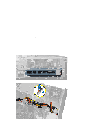
System Board Layout The following image displays the system board layout of the computer. 1. PCI Express x16 (wired as x4) connector 2. PCI Card connector 3. PCI Express x1 Card connector 4. Battery socket 5. PCI Express x16 card connector 6. Intruder Connector (Intruder) 7. Fan Connector (Fan_SYS) 8. Power connector (12V_PWRCONN) 9. Processor 36 10. Fan Connector (Fan_CPU) 11. Memory Module Connectors (DIMM_1-4) 12. Power Switch Connector (PWR_SW) 13. System power Connector (Mini_PWR) 14. SATA Drive Connectors 15. Front USB 16. Internal Speaker Connector 17. Front-Panel Connector (FrontPanel) 18. Thermal Sensor Connector
-
 1
1 -
2
-
3
-
4
-
5
-
6
-
7
-
8
-
9
-
10
-
11
-
12
-
13
-
14
-
15
-
16
-
17
-
18
-
19
-
20
-
21
-
22
-
23
-
24
-
25
-
26
-
27
-
28
-
29
-
30
-
 31
31 -
 32
32 -
 33
33 -
 34
34 -
 35
35 -
 36
36 -
 37
37 -
 38
38 -
 39
39 -
 40
40 -
 41
41 -
42
-
43
-
44
-
45
-
46
-
47
-
48
-
49
-
50
-
51
-
52
-
53
-
54
-
55
-
56
-
57
-
58
-
59
-
60
-
61
-
62
-
63
-
64
-
65
 |
 |
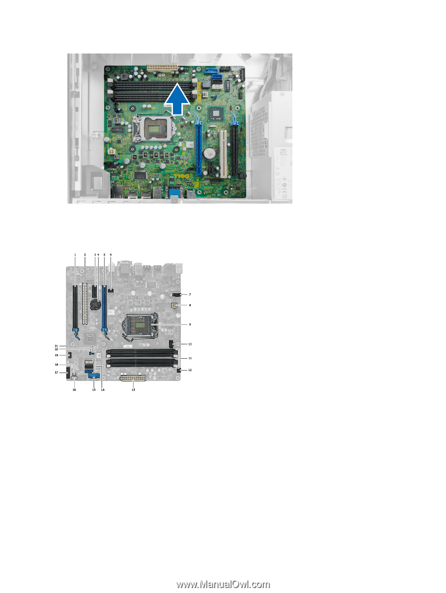
System Board Layout
The following image displays the system board layout of the computer.
1.
PCI Express x16 (wired as x4) connector
2.
PCI Card connector
3.
PCI Express x1 Card connector
4.
Battery socket
5.
PCI Express x16 card connector
6.
Intruder Connector (Intruder)
7.
Fan Connector (Fan_SYS)
8.
Power connector (12V_PWRCONN)
9.
Processor
10.
Fan Connector (Fan_CPU)
11.
Memory Module Connectors (DIMM_1-4)
12.
Power Switch Connector (PWR_SW)
13.
System power Connector (Mini_PWR)
14.
SATA Drive Connectors
15.
Front USB
16.
Internal Speaker Connector
17.
Front-Panel Connector (FrontPanel)
18.
Thermal Sensor Connector
36