Dell OptiPlex GX260 Service Manual - Page 78
Microprocessor Installation, microprocessor and the computer.
 |
View all Dell OptiPlex GX260 manuals
Add to My Manuals
Save this manual to your list of manuals |
Page 78 highlights
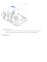
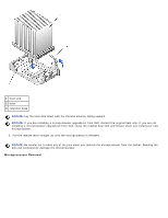
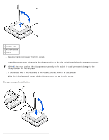
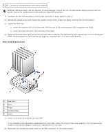
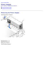
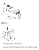
1 release lever 2 microprocessor 3 socket 6. Remove the microprocessor from the socket. Leave the release lever extended in the release position so that the socket is ready for the new microprocessor. NOTICE: You must position the microprocessor correctly in the socket to avoid permanent damage to the microprocessor and the computer. 7. If the release lever is not extended to the release position, move it to that position. 8. Align pin 1 (the imprinted corner) of the microprocessor and pin 1 of the socket. Microprocessor Installation
-
 1
1 -
2
-
3
-
4
-
5
-
6
-
7
-
8
-
9
-
10
-
11
-
12
-
13
-
14
-
15
-
16
-
17
-
18
-
19
-
20
-
21
-
22
-
23
-
24
-
25
-
26
-
27
-
28
-
29
-
30
-
31
-
32
-
33
-
34
-
35
-
36
-
37
-
38
-
39
-
40
-
41
-
42
-
43
-
44
-
45
-
46
-
47
-
48
-
49
-
50
-
51
-
52
-
53
-
54
-
55
-
56
-
57
-
58
-
59
-
60
-
61
-
62
-
63
-
64
-
65
-
66
-
67
-
68
-
69
-
70
-
71
-
72
-
 73
73 -
 74
74 -
 75
75 -
 76
76 -
 77
77 -
 78
78 -
 79
79 -
 80
80 -
 81
81 -
 82
82 -
 83
83 -
84
-
85
-
86
-
87
-
88
-
89
-
90
-
91
-
92
-
93
-
94
-
95
-
96
-
97
-
98
-
99
-
100
 |
 |

1
release lever
2
microprocessor
3
socket
6. Remove the microprocessor from the socket.
Leave the release lever extended in the release position so that the socket is ready for the new microprocessor.
NOTICE:
You must position the microprocessor correctly in the socket to avoid permanent damage to the
microprocessor and the computer.
7. If the release lever is not extended to the release position, move it to that position.
8. Align pin 1 (the imprinted corner) of the microprocessor and pin 1 of the socket.
Microprocessor Installation