Dell OptiPlex GX260 Service Manual - Page 85
Removing the System Board, System Board Jumpers
 |
View all Dell OptiPlex GX260 manuals
Add to My Manuals
Save this manual to your list of manuals |
Page 85 highlights
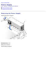
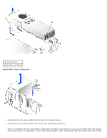
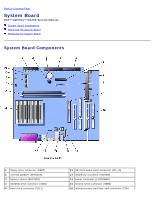
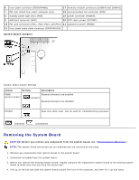
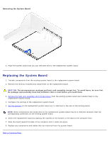
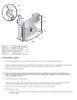
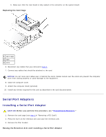
6 front-panel connector (FRONTPANEL) 17 memory module connectors (DIMM A and DIMM B) 7 PCI riser (small mini-tower computer only) 18 microprocessor fan connector (FAN) 8 standby power light (AUX_PWR) 19 power connector (POWER) 9 AGP card connector (AGP) 20 RTC reset jumper (RTCRST) 10 PCI card connectors (PCI1, PCI2, PCI3, and PCI4) 21 password jumper (PSWD) 11 front-panel audio cable connector (FRONTAUDIO) System Board Jumpers System-Board Jumper Settings Jumper Setting Description PSWD (green jumper) Password features are enabled. (default) Password features are disabled. RTCRST Real-time clock reset. Can be used for troubleshooting purposes. jumpered unjumpered Removing the System Board CAUTION: Before you remove any component from the system board, see "Precautionary Measures." NOTE: The system board and metal tray are attached and are removed as one piece. 1. Remove any components that restrict access to the system board. 2. Disconnect all cables from the system board. 3. Before you remove the existing system board, visually compare the replacement system board to the existing system board to make sure that you have the correct part. 4. Pull up on the tab and slide the system board toward the front of the computer, and then lift it up and away.
-
 1
1 -
2
-
3
-
4
-
5
-
6
-
7
-
8
-
9
-
10
-
11
-
12
-
13
-
14
-
15
-
16
-
17
-
18
-
19
-
20
-
21
-
22
-
23
-
24
-
25
-
26
-
27
-
28
-
29
-
30
-
31
-
32
-
33
-
34
-
35
-
36
-
37
-
38
-
39
-
40
-
41
-
42
-
43
-
44
-
45
-
46
-
47
-
48
-
49
-
50
-
51
-
52
-
53
-
54
-
55
-
56
-
57
-
58
-
59
-
60
-
61
-
62
-
63
-
64
-
65
-
66
-
67
-
68
-
69
-
70
-
71
-
72
-
73
-
74
-
75
-
76
-
77
-
78
-
79
-
 80
80 -
 81
81 -
 82
82 -
 83
83 -
 84
84 -
 85
85 -
 86
86 -
 87
87 -
 88
88 -
 89
89 -
 90
90 -
91
-
92
-
93
-
94
-
95
-
96
-
97
-
98
-
99
-
100
 |
 |
