Dell PowerConnect J-EX4500 Hardware Guide - Page 34
Field-Replaceable Units in J-EX4500 Switches
 |
View all Dell PowerConnect J-EX4500 manuals
Add to My Manuals
Save this manual to your list of manuals |
Page 34 highlights
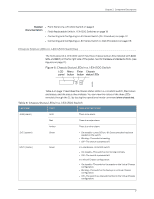
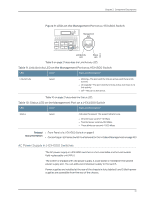
Dell PowerConnect J-Series J-EX4500 Ethernet Switch Hardware Guide A major alarm (red) indicates a critical error condition that requires immediate action. A minor alarm (amber) indicates a noncritical condition that requires monitoring or maintenance. A minor alarm that is left unchecked might cause interruption in service or performance degradation. All three LEDs can be lit simultaneously. Related Documentation • Front Panel of a J-EX4500 Switch on page 8 • For information about checking active alarms with the J-Web interface and understanding alarm types and severity levels, see the Dell PowerConnect J-Series Ethernet Switch Complete Software Guide for Junos OS at http://www.support.dell.com/manuals. Field-Replaceable Units in J-EX4500 Switches Field-replaceable units (FRUs) are components that you can replace at your site. The field-replaceable units (FRUs) in J-EX4500 switches are: • Power supplies • Fan tray • Uplink module(s) • Virtual Chassis module • SFP+ transceivers • SFP transceivers NOTE: Uplink modules, transceivers, Virtual Chassis cables, and Virtual Chassis cable connector retainers are not part of the standard package and must be ordered separately. The power supplies, fan tray, uplink module(s), and transceivers are hot-removable and hot-insertable: You can remove and replace them without powering off the switch or disrupting switch functions. The Virtual Chassis module is offline field-replaceable: You can remove and replace the module, but the switch must be powered off first. Related • Installing and Removing J-EX4500 Switch Hardware Components on page 87 Documentation Network Port and Uplink Module Port LEDs in J-EX4500 Switches Each network port and uplink module port on a J-EX4500 switch has two LEDs that indicate link/activity and status. The figures in this topic show the location of these LEDs: 18
-
 1
1 -
2
-
3
-
4
-
5
-
6
-
7
-
8
-
9
-
10
-
11
-
12
-
13
-
14
-
15
-
16
-
17
-
18
-
19
-
20
-
21
-
22
-
23
-
24
-
25
-
26
-
27
-
28
-
 29
29 -
 30
30 -
 31
31 -
 32
32 -
 33
33 -
 34
34 -
 35
35 -
 36
36 -
 37
37 -
 38
38 -
 39
39 -
40
-
41
-
42
-
43
-
44
-
45
-
46
-
47
-
48
-
49
-
50
-
51
-
52
-
53
-
54
-
55
-
56
-
57
-
58
-
59
-
60
-
61
-
62
-
63
-
64
-
65
-
66
-
67
-
68
-
69
-
70
-
71
-
72
-
73
-
74
-
75
-
76
-
77
-
78
-
79
-
80
-
81
-
82
-
83
-
84
-
85
-
86
-
87
-
88
-
89
-
90
-
91
-
92
-
93
-
94
-
95
-
96
-
97
-
98
-
99
-
100
-
101
-
102
-
103
-
104
-
105
-
106
-
107
-
108
-
109
-
110
-
111
-
112
-
113
-
114
-
115
-
116
-
117
-
118
-
119
-
120
-
121
-
122
-
123
-
124
-
125
-
126
-
127
-
128
-
129
-
130
-
131
-
132
-
133
-
134
-
135
-
136
-
137
-
138
-
139
-
140
-
141
-
142
-
143
-
144
-
145
-
146
-
147
-
148
-
149
-
150
-
151
-
152
-
153
-
154
-
155
-
156
-
157
-
158
-
159
-
160
-
161
-
162
-
163
-
164
-
165
-
166
-
167
-
168
-
169
-
170
-
171
-
172
-
173
-
174
-
175
-
176
-
177
-
178
-
179
-
180
-
181
-
182
-
183
-
184
-
185
-
186
-
187
-
188
-
189
-
190
-
191
-
192
-
193
-
194
-
195
-
196
-
197
-
198
-
199
-
200
-
201
-
202
-
203
-
204
-
205
-
206
-
207
-
208
-
209
-
210
-
211
-
212
-
213
-
214
-
215
-
216
-
217
-
218
-
219
-
220
-
221
-
222
-
223
-
224
-
225
-
226
 |
 |
