Dell PowerConnect J-EX4500 Hardware Guide - Page 45
Virtual Chassis Module in J-EX4500 Switches, Table 12: Uplink Module Status LED
 |
View all Dell PowerConnect J-EX4500 manuals
Add to My Manuals
Save this manual to your list of manuals |
Page 45 highlights
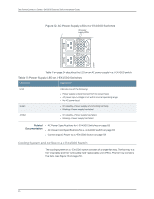
Chapter 2: Component Descriptions Table 12: Uplink Module Status LED LED State Description ST (status) Unlit Green • The uplink module is offline. • The chassis is powered off. • The uplink module is online and functioning normally. Each uplink module port has a pair of LEDs that indicate the link/activity and status of the port. See "Network Port and Uplink Module Port LEDs in J-EX4500 Switches" on page 18 for details about the uplink module port LEDs. The SFP+ uplink modules are shipped with dust covers preinstalled in the ports. Related Documentation • Network Port and Uplink Module Port LEDs in J-EX4500 Switches on page 18 • Network Port and Uplink Module Port Connector Pinout Information for J-EX4500 Switches on page 35 • Optical Interface Support in J-EX4500 Switches on page 40 • SFP+ Direct Attach Cables for J-EX Series Switches on page 46 • For an overview of J-EX Series Ethernet switch interfaces, see the see the Dell PowerConnect J-Series Ethernet Switch Complete Software Guide for Junos OS at http://www.support.dell.com/manuals. • Installing an Uplink Module in a J-EX4500 Switch on page 91 • Removing an Uplink Module from a J-EX4500 Switch on page 131 Virtual Chassis Module in J-EX4500 Switches The Virtual Chassis module is installed horizontally on the rear panel of a J-EX4500 switch chassis. The Virtual Chassis module has two dedicated Virtual Chassis ports (VCPs) that can be used to interconnect the J-EX4500 switch with a J-EX4200 switch or a J-EX4500 switch in a Virtual Chassis configuration. The module is an offline field-replaceable unit (FRU). The Virtual Chassis module comes preinstalled in the switch chassis. NOTE: Virtual Chassis cables and cable connector retainers are not part of the J-EX4500 switch shipping configuration and must be purchased separately. CAUTION: Operating a J-EX4500 switch without the Virtual Chassis module installed is not supported. You cannot start the switch unless the Virtual Chassis module is installed in the chassis. 29
-
 1
1 -
2
-
3
-
4
-
5
-
6
-
7
-
8
-
9
-
10
-
11
-
12
-
13
-
14
-
15
-
16
-
17
-
18
-
19
-
20
-
21
-
22
-
23
-
24
-
25
-
26
-
27
-
28
-
29
-
30
-
31
-
32
-
33
-
34
-
35
-
36
-
37
-
38
-
39
-
 40
40 -
 41
41 -
 42
42 -
 43
43 -
 44
44 -
 45
45 -
 46
46 -
 47
47 -
 48
48 -
 49
49 -
 50
50 -
51
-
52
-
53
-
54
-
55
-
56
-
57
-
58
-
59
-
60
-
61
-
62
-
63
-
64
-
65
-
66
-
67
-
68
-
69
-
70
-
71
-
72
-
73
-
74
-
75
-
76
-
77
-
78
-
79
-
80
-
81
-
82
-
83
-
84
-
85
-
86
-
87
-
88
-
89
-
90
-
91
-
92
-
93
-
94
-
95
-
96
-
97
-
98
-
99
-
100
-
101
-
102
-
103
-
104
-
105
-
106
-
107
-
108
-
109
-
110
-
111
-
112
-
113
-
114
-
115
-
116
-
117
-
118
-
119
-
120
-
121
-
122
-
123
-
124
-
125
-
126
-
127
-
128
-
129
-
130
-
131
-
132
-
133
-
134
-
135
-
136
-
137
-
138
-
139
-
140
-
141
-
142
-
143
-
144
-
145
-
146
-
147
-
148
-
149
-
150
-
151
-
152
-
153
-
154
-
155
-
156
-
157
-
158
-
159
-
160
-
161
-
162
-
163
-
164
-
165
-
166
-
167
-
168
-
169
-
170
-
171
-
172
-
173
-
174
-
175
-
176
-
177
-
178
-
179
-
180
-
181
-
182
-
183
-
184
-
185
-
186
-
187
-
188
-
189
-
190
-
191
-
192
-
193
-
194
-
195
-
196
-
197
-
198
-
199
-
200
-
201
-
202
-
203
-
204
-
205
-
206
-
207
-
208
-
209
-
210
-
211
-
212
-
213
-
214
-
215
-
216
-
217
-
218
-
219
-
220
-
221
-
222
-
223
-
224
-
225
-
226
 |
 |
