Dell PowerConnect J-EX4500 Hardware Guide - Page 96
Attaching the Mounting Bracket Along the Front of the Switch
 |
View all Dell PowerConnect J-EX4500 manuals
Add to My Manuals
Save this manual to your list of manuals |
Page 96 highlights
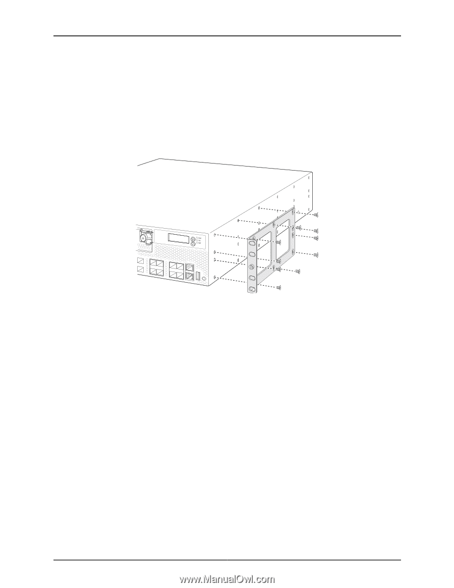
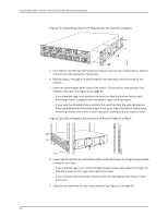
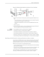
g020818 Dell PowerConnect J-Series J-EX4500 Ethernet Switch Hardware Guide b. To ensure that the switch chassis is level after installation, verify that the cage nuts on one side of the rack are aligned with the cage nuts on the other side. 2. Place the switch on a flat, stable surface. 3. Align the mounting brackets along the front or rear of the side panels of the switch chassis depending on whether you are front-mounting or rear-mounting the switch. See Figure 27 on page 80. Figure 27: Attaching the Mounting Bracket Along the Front of the Switch 4. Align the bottom holes in the mounting brackets with holes on the side panels of the switch chassis. 5. Insert mounting screws into the aligned holes. Tighten the screws. 6. Ensure that the other holes in the mounting brackets are aligned with the holes in the side panels. Insert a screw in each hole and tighten the screws. 7. Have one person grasp both sides of the switch, lift the switch, and position it as follows in the rack. See Figure 28 on page 81. • If you installed cage nuts, align the bottom hole in each bracket with the bottom cage nut in each post. • If your rack has threaded holes, align the mounting bracket holes with the threaded holes in the rack rail, and align the bottom hole in each bracket with a hole in each post, making sure the chassis is level. 80
-
 1
1 -
2
-
3
-
4
-
5
-
6
-
7
-
8
-
9
-
10
-
11
-
12
-
13
-
14
-
15
-
16
-
17
-
18
-
19
-
20
-
21
-
22
-
23
-
24
-
25
-
26
-
27
-
28
-
29
-
30
-
31
-
32
-
33
-
34
-
35
-
36
-
37
-
38
-
39
-
40
-
41
-
42
-
43
-
44
-
45
-
46
-
47
-
48
-
49
-
50
-
51
-
52
-
53
-
54
-
55
-
56
-
57
-
58
-
59
-
60
-
61
-
62
-
63
-
64
-
65
-
66
-
67
-
68
-
69
-
70
-
71
-
72
-
73
-
74
-
75
-
76
-
77
-
78
-
79
-
80
-
81
-
82
-
83
-
84
-
85
-
86
-
87
-
88
-
89
-
90
-
 91
91 -
 92
92 -
 93
93 -
 94
94 -
 95
95 -
 96
96 -
 97
97 -
 98
98 -
 99
99 -
 100
100 -
 101
101 -
102
-
103
-
104
-
105
-
106
-
107
-
108
-
109
-
110
-
111
-
112
-
113
-
114
-
115
-
116
-
117
-
118
-
119
-
120
-
121
-
122
-
123
-
124
-
125
-
126
-
127
-
128
-
129
-
130
-
131
-
132
-
133
-
134
-
135
-
136
-
137
-
138
-
139
-
140
-
141
-
142
-
143
-
144
-
145
-
146
-
147
-
148
-
149
-
150
-
151
-
152
-
153
-
154
-
155
-
156
-
157
-
158
-
159
-
160
-
161
-
162
-
163
-
164
-
165
-
166
-
167
-
168
-
169
-
170
-
171
-
172
-
173
-
174
-
175
-
176
-
177
-
178
-
179
-
180
-
181
-
182
-
183
-
184
-
185
-
186
-
187
-
188
-
189
-
190
-
191
-
192
-
193
-
194
-
195
-
196
-
197
-
198
-
199
-
200
-
201
-
202
-
203
-
204
-
205
-
206
-
207
-
208
-
209
-
210
-
211
-
212
-
213
-
214
-
215
-
216
-
217
-
218
-
219
-
220
-
221
-
222
-
223
-
224
-
225
-
226
 |
 |