Dell PowerConnect W-Airwave W-Airwave 7.4 User Guide - Page 271
Adding an IDF,
 |
View all Dell PowerConnect W-Airwave manuals
Add to My Manuals
Save this manual to your list of manuals |
Page 271 highlights
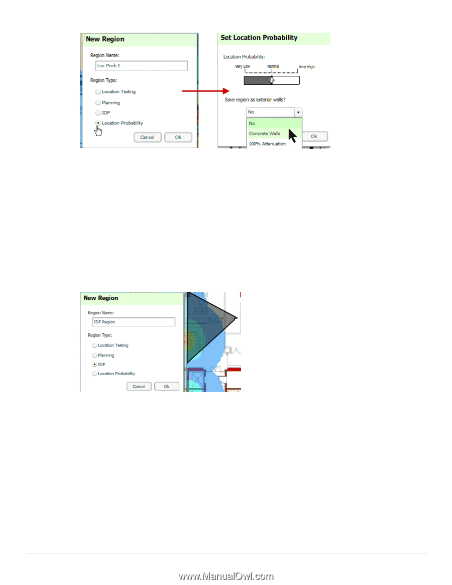
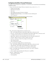
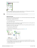
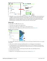
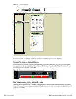
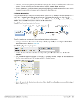
Figure 201 Adding a New Location Probability Region 5. Optionally, you can save the location region as the exterior walls. 100% attenuation can be selected to force VisualRF to only place devices inside of the selected region. No device will ever be placed outside of the probability region when 100% attenuation is selected. 100% attenuation is only recommended for tall buildings where it is extremely unlikely that any user is located outside of the building. No heat map or attenuation grid is calculated for devices outside of the 100% attenuation region. Adding an IDF To add an IDF to VisualRF, follow these steps: 1. In the Edit menu, select the Draw Region option. 2. Outline the desired IDF region. Double-click to end the outline process. 3. Name the region, select a Region Type of IDF, and select OK, as shown in Figure 202. Figure 202 Adding a new IDF Region Now that the IDF is defined you will see a green IDF icon on your floor plan. Double click that icon to navigate into the IDF. 1. Add a rack to the IDF by selecting the Add Empty Rack icon and dragging it to the background. 2. To add a planned device, select the Add Planned Device icon to view the Manually Provision Rack Gear menu. Select the device type in the Type menu, and then find the device you want to add. Drag it into the rack at the appropriate location. 3. To add a wired device that is currently being monitored by AMP, select Add Deployed Device. 4. Locate the device to be added. 5. Drag the device to the appropriate location in the rack, as shown in Figure 203. Dell PowerConnect W-AirWave 7.4 | User Guide Using VisualRF | 271
-
 1
1 -
2
-
3
-
4
-
5
-
6
-
7
-
8
-
9
-
10
-
11
-
12
-
13
-
14
-
15
-
16
-
17
-
18
-
19
-
20
-
21
-
22
-
23
-
24
-
25
-
26
-
27
-
28
-
29
-
30
-
31
-
32
-
33
-
34
-
35
-
36
-
37
-
38
-
39
-
40
-
41
-
42
-
43
-
44
-
45
-
46
-
47
-
48
-
49
-
50
-
51
-
52
-
53
-
54
-
55
-
56
-
57
-
58
-
59
-
60
-
61
-
62
-
63
-
64
-
65
-
66
-
67
-
68
-
69
-
70
-
71
-
72
-
73
-
74
-
75
-
76
-
77
-
78
-
79
-
80
-
81
-
82
-
83
-
84
-
85
-
86
-
87
-
88
-
89
-
90
-
91
-
92
-
93
-
94
-
95
-
96
-
97
-
98
-
99
-
100
-
101
-
102
-
103
-
104
-
105
-
106
-
107
-
108
-
109
-
110
-
111
-
112
-
113
-
114
-
115
-
116
-
117
-
118
-
119
-
120
-
121
-
122
-
123
-
124
-
125
-
126
-
127
-
128
-
129
-
130
-
131
-
132
-
133
-
134
-
135
-
136
-
137
-
138
-
139
-
140
-
141
-
142
-
143
-
144
-
145
-
146
-
147
-
148
-
149
-
150
-
151
-
152
-
153
-
154
-
155
-
156
-
157
-
158
-
159
-
160
-
161
-
162
-
163
-
164
-
165
-
166
-
167
-
168
-
169
-
170
-
171
-
172
-
173
-
174
-
175
-
176
-
177
-
178
-
179
-
180
-
181
-
182
-
183
-
184
-
185
-
186
-
187
-
188
-
189
-
190
-
191
-
192
-
193
-
194
-
195
-
196
-
197
-
198
-
199
-
200
-
201
-
202
-
203
-
204
-
205
-
206
-
207
-
208
-
209
-
210
-
211
-
212
-
213
-
214
-
215
-
216
-
217
-
218
-
219
-
220
-
221
-
222
-
223
-
224
-
225
-
226
-
227
-
228
-
229
-
230
-
231
-
232
-
233
-
234
-
235
-
236
-
237
-
238
-
239
-
240
-
241
-
242
-
243
-
244
-
245
-
246
-
247
-
248
-
249
-
250
-
251
-
252
-
253
-
254
-
255
-
256
-
257
-
258
-
259
-
260
-
261
-
262
-
263
-
264
-
265
-
 266
266 -
 267
267 -
 268
268 -
 269
269 -
 270
270 -
 271
271 -
 272
272 -
 273
273 -
 274
274 -
 275
275 -
 276
276 -
277
-
278
-
279
-
280
-
281
-
282
-
283
-
284
-
285
-
286
-
287
-
288
-
289
-
290
-
291
-
292
-
293
-
294
-
295
-
296
-
297
-
298
-
299
-
300
-
301
-
302
-
303
-
304
-
305
-
306
-
307
-
308
-
309
-
310
 |
 |