Dell PowerEdge 1650 Rack Installation Guide - Page 19
cable slack at the hinge positions, and secure the cables to the cable-management - power
 |
View all Dell PowerEdge 1650 manuals
Add to My Manuals
Save this manual to your list of manuals |
Page 19 highlights
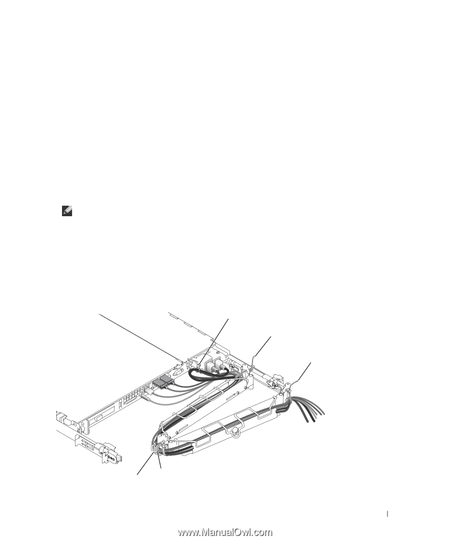
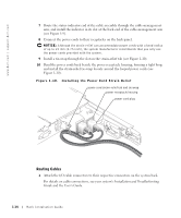
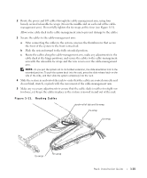
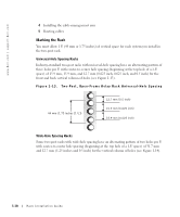
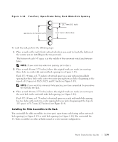
2 Route the power and I/O cables through the cable-management arm, using four loosely secured releasable tie wraps (two in the middle and on each end of the cablemanagement arm). Do not fully tighten the tie wraps at this time (see Figure 1-11). Allow some cable slack in the cable-management arm to prevent damage to the cables. 3 Secure the cables to the cable-management arm: a After connecting the cables to the system, unscrew the thumbscrews that secure the front of the system to the front vertical rail. b Slide the system forward to the fully extended position. c Route the cables along the cable-management arm, make any adjustments to the cable slack at the hinge positions, and secure the cables to the cable-management arm with the releasable tie wraps and the wire covers over the cable-management arm. NOTE: As you pull the system out to its furthest extension, the slide assemblies lock in the extended position. To push the system back into the rack, press the slide release latch on the side of the slide, and then slide the system completely into the rack. 4 Slide the system in and out of the rack to verify that the cables are routed correctly and do not bind, stretch, or pinch with the movement of the cable-management arm. 5 Make any necessary adjustments to ensure that the cable slack is neither too tight nor too loose, yet keeps the cables in place as the system is moved in and out of the rack. Figure 1-11. Routing Cables strain-relief tab and tie-wrap tie-wrap tie-wrap tie-wrap tie-wrap Rack Installation Guide 1-15
-
 1
1 -
2
-
3
-
4
-
5
-
6
-
7
-
8
-
9
-
10
-
11
-
12
-
13
-
 14
14 -
 15
15 -
 16
16 -
 17
17 -
 18
18 -
 19
19 -
 20
20 -
 21
21 -
 22
22 -
 23
23 -
 24
24 -
25
-
26
-
27
-
28
-
29
-
30
-
31
-
32
-
33
-
34
-
35
-
36
-
37
-
38
-
39
-
40
-
41
-
42
-
43
-
44
-
45
-
46
-
47
-
48
-
49
-
50
-
51
-
52
-
53
-
54
-
55
-
56
-
57
-
58
-
59
-
60
-
61
-
62
-
63
-
64
-
65
-
66
-
67
-
68
-
69
-
70
-
71
-
72
-
73
-
74
-
75
-
76
-
77
-
78
-
79
-
80
-
81
-
82
-
83
-
84
-
85
-
86
-
87
-
88
-
89
-
90
-
91
-
92
-
93
-
94
-
95
-
96
-
97
-
98
-
99
-
100
-
101
-
102
-
103
-
104
-
105
-
106
-
107
-
108
-
109
-
110
-
111
-
112
-
113
-
114
-
115
-
116
-
117
-
118
-
119
-
120
-
121
-
122
-
123
-
124
-
125
-
126
-
127
-
128
-
129
-
130
-
131
-
132
-
133
-
134
-
135
-
136
-
137
-
138
-
139
-
140
-
141
-
142
-
143
-
144
-
145
-
146
-
147
-
148
-
149
-
150
-
151
-
152
-
153
-
154
-
155
-
156
-
157
-
158
-
159
-
160
-
161
-
162
-
163
-
164
-
165
-
166
-
167
-
168
-
169
-
170
-
171
-
172
-
173
-
174
-
175
-
176
-
177
 |
 |