Dell PowerEdge 1650 Rack Installation Guide - Page 29
Installing the System in the Rack
 |
View all Dell PowerEdge 1650 manuals
Add to My Manuals
Save this manual to your list of manuals |
Page 29 highlights
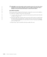
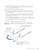
12 Install the stiffening bracket into the appropriate holes at the back of the slide assemblies and secure the bracket with a 12-24 x 0.5-inch pan-head Phillips screw on each slide assembly (see Figure 1-16). If the vertical rack is 3 inches wide, use the holes at the back end of the slide assemblies (shown in Figure 1-16). If the vertical rack is 6 inches wide, use the holes located 3 inches in front of the holes at the back end of the slide assemblies. Installing the System in the Rack CAUTION: Due to the size and weight of the system, never attempt to install the system by yourself. NOTE: The procedure for installing a system into a rack is identical for flush-mounted and center-mounted support trays. 1 Pull the slides out to their fully extended position. CAUTION: Because of the size and weight of the system, never attempt to install the system in the slide assemblies by yourself. 2 Remove the system front bezel: a Unlock the keylock. b Press the right- and left-end tabs. c Pull the bezel away from the system. 3 Lift the system into position (see Figure 1-18). 4 Place one hand on the front-bottom of the system and the other hand on the backbottom of the system. 5 Tilt the back of the system down while aligning the back shoulder screws on the sides of the system with the back slots on the slide assemblies. 6 Engage the back shoulder screws into their slots. 7 Lower the front of the system and engage the front shoulder screws in the front slot behind the system release latch (see Figure 1-18). The system release latch will move forward and then snap back as the front shoulder screw passes into the front slot. Use this system release latch when you wish to remove the system from the slide assemblies. Rack Installation Guide 1-25
-
 1
1 -
2
-
3
-
4
-
5
-
6
-
7
-
8
-
9
-
10
-
11
-
12
-
13
-
14
-
15
-
16
-
17
-
18
-
19
-
20
-
21
-
22
-
23
-
 24
24 -
 25
25 -
 26
26 -
 27
27 -
 28
28 -
 29
29 -
 30
30 -
 31
31 -
 32
32 -
 33
33 -
 34
34 -
35
-
36
-
37
-
38
-
39
-
40
-
41
-
42
-
43
-
44
-
45
-
46
-
47
-
48
-
49
-
50
-
51
-
52
-
53
-
54
-
55
-
56
-
57
-
58
-
59
-
60
-
61
-
62
-
63
-
64
-
65
-
66
-
67
-
68
-
69
-
70
-
71
-
72
-
73
-
74
-
75
-
76
-
77
-
78
-
79
-
80
-
81
-
82
-
83
-
84
-
85
-
86
-
87
-
88
-
89
-
90
-
91
-
92
-
93
-
94
-
95
-
96
-
97
-
98
-
99
-
100
-
101
-
102
-
103
-
104
-
105
-
106
-
107
-
108
-
109
-
110
-
111
-
112
-
113
-
114
-
115
-
116
-
117
-
118
-
119
-
120
-
121
-
122
-
123
-
124
-
125
-
126
-
127
-
128
-
129
-
130
-
131
-
132
-
133
-
134
-
135
-
136
-
137
-
138
-
139
-
140
-
141
-
142
-
143
-
144
-
145
-
146
-
147
-
148
-
149
-
150
-
151
-
152
-
153
-
154
-
155
-
156
-
157
-
158
-
159
-
160
-
161
-
162
-
163
-
164
-
165
-
166
-
167
-
168
-
169
-
170
-
171
-
172
-
173
-
174
-
175
-
176
-
177
 |
 |