Dell PowerEdge 1650 Rack Installation Guide - Page 27
Secure each front center mount bracket by its nuts and shoulder washers finger tight
 |
View all Dell PowerEdge 1650 manuals
Add to My Manuals
Save this manual to your list of manuals |
Page 27 highlights
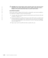
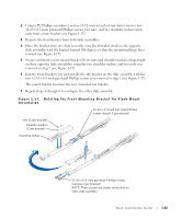
2 Using a #2 Phillips screwdriver and an 11/32-inch wrench or nut driver, remove two 12-24 x 0.5-inch pan-head Phillips screws, two nuts, and two shoulder washers from each front center bracket (see Figure 1-17). 3 Remove the front bracket from both slide assemblies. 4 Place the bracket from one slide assembly onto the threaded studs on the opposite slide assembly, with the bracket turned 180 degrees so that the mounting flange faces forward (see Figure 1-17). 5 Secure each front center mount bracket (by its nuts and shoulder washers) finger tight on their opposite slide assemblies using the two shoulder washers and two nuts you removed in step 2 (see Figure 1-17). 6 Join the front brackets you just installed to the bracket on the slide assembly with the two 12-24 x 0.5-inch pan-head Phillips screws you removed in step 2 (see Figure 1-17). The joined bracket becomes the new extended rear bracket. 7 Repeat steps 4 through 6 to configure the other slide assembly. Figure 1-17. Rotating the Front Mounting Bracket for Flush-Mount Installation 12-24 x 0.5-inch pan-head Phillips screws (install 2 per bracket) nuts (2 per bracket) shoulder washers (2 per bracket) mounting flange 12-24 x 0.5-inch pan-head Phillips screws (remove 2 per bracket) NOTE: These screws are shown reinstalled on other slide assembly. Rack Installation Guide 1-23
-
 1
1 -
2
-
3
-
4
-
5
-
6
-
7
-
8
-
9
-
10
-
11
-
12
-
13
-
14
-
15
-
16
-
17
-
18
-
19
-
20
-
21
-
 22
22 -
 23
23 -
 24
24 -
 25
25 -
 26
26 -
 27
27 -
 28
28 -
 29
29 -
 30
30 -
 31
31 -
 32
32 -
33
-
34
-
35
-
36
-
37
-
38
-
39
-
40
-
41
-
42
-
43
-
44
-
45
-
46
-
47
-
48
-
49
-
50
-
51
-
52
-
53
-
54
-
55
-
56
-
57
-
58
-
59
-
60
-
61
-
62
-
63
-
64
-
65
-
66
-
67
-
68
-
69
-
70
-
71
-
72
-
73
-
74
-
75
-
76
-
77
-
78
-
79
-
80
-
81
-
82
-
83
-
84
-
85
-
86
-
87
-
88
-
89
-
90
-
91
-
92
-
93
-
94
-
95
-
96
-
97
-
98
-
99
-
100
-
101
-
102
-
103
-
104
-
105
-
106
-
107
-
108
-
109
-
110
-
111
-
112
-
113
-
114
-
115
-
116
-
117
-
118
-
119
-
120
-
121
-
122
-
123
-
124
-
125
-
126
-
127
-
128
-
129
-
130
-
131
-
132
-
133
-
134
-
135
-
136
-
137
-
138
-
139
-
140
-
141
-
142
-
143
-
144
-
145
-
146
-
147
-
148
-
149
-
150
-
151
-
152
-
153
-
154
-
155
-
156
-
157
-
158
-
159
-
160
-
161
-
162
-
163
-
164
-
165
-
166
-
167
-
168
-
169
-
170
-
171
-
172
-
173
-
174
-
175
-
176
-
177
 |
 |
