Dell PowerEdge C5230 Dell Systems Hardware Owners Manual
Dell PowerEdge C5230 Manual
 |
View all Dell PowerEdge C5230 manuals
Add to My Manuals
Save this manual to your list of manuals |
Dell PowerEdge C5230 manual content summary:
- Dell PowerEdge C5230 | Dell Systems Hardware Owners Manual - Page 1
Dell PowerEdge C5230 Systems Hardware Owner's Manual Regulatory Model: B04S - Dell PowerEdge C5230 | Dell Systems Hardware Owners Manual - Page 2
A CAUTION indicates potential damage to hardware or loss of data if instructions are not followed. WARNING: A WARNING indicates a potential for property permission of Dell Inc. is strictly forbidden. Trademarks used in this text: Dell™, the DELL logo, and PowerEdge™ are trademarks of Dell Inc. Intel - Dell PowerEdge C5230 | Dell Systems Hardware Owners Manual - Page 3
Contents 1 Important Information 5 2 About Your System 6 Front-Panel Features and Indicators 7 3 Using the System Setup Program 11 Start Menu 11 BIOS Setup Options at Boot 12 Console Redirection 12 Configuring Special Keys 13 General Help 14 Server Platform Setup Utility Screens 15 Main - Dell PowerEdge C5230 | Dell Systems Hardware Owners Manual - Page 4
Sled Configuration 101 Sleds 102 Memory Modules 105 Hard Drives 109 Hard Drive Boards 116 Heat Sinks 119 Processors 123 5 Troubleshooting 127 Troubleshooting Sequence 127 Update Utilities 131 BIOS System Update 136 BIOS Recovery Mode 136 6 Jumpers and Connectors 137 System Board Jumpers - Dell PowerEdge C5230 | Dell Systems Hardware Owners Manual - Page 5
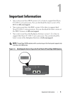
have the Backplane firmware version 1.12 or later to support Intel Xeon E3-1200 v3 series processors. You can download the latest version of the Backplane firmware at dell.com/support. NOTE: PowerEdge C5230 systems with a service tag on the front panel support only Intel Xeon E3-1200 series. Figure - Dell PowerEdge C5230 | Dell Systems Hardware Owners Manual - Page 6
About Your System The system includes the following configurations: • 12-sled system supporting 3.5 inch hard drives. • 12-sled system supporting 2.5 inch hard drives. NOTE: Supporting SATA drive only, SAS driver is not supported. 6 About Your System - Dell PowerEdge C5230 | Dell Systems Hardware Owners Manual - Page 7
Panel Features and Indicators The Dell PowerEdge C5230 server is available in a 12-sled system supporting either two 3.5-inch or four Counterclockwise 90°) 1 8 76 5 4 3 2 Item Feature Description 1 Service Tag Identifying service tag 2 Y-cable connector USB (x2) + VGA 3 NIC1 LAN port - Dell PowerEdge C5230 | Dell Systems Hardware Owners Manual - Page 8
Indicators Figure 1-3. Front Panel Indicators (Rotated Counterclockwise 90°) 1 23 4 8 7 65 Item Feature 2, 4 LAN link LED 1, 3 LAN activity LED LAN link LED LAN activity LED LAN link LED LAN activity LED LAN link LED LAN activity LED LAN link LED LAN activity LED 5 Power LED - Dell PowerEdge C5230 | Dell Systems Hardware Owners Manual - Page 9
6 Hard drive activity Blinking green Hard drive 0 active LEDs Hard drive 1 active Hard drive 2 active Hard drive 3 active 7 Status LED Amber Normal status Off Blinking amber Event occurred in the system 8 Identity LED Blue Identifies the system On Normal status Blue Identifies - Dell PowerEdge C5230 | Dell Systems Hardware Owners Manual - Page 10
10 About Your System - Dell PowerEdge C5230 | Dell Systems Hardware Owners Manual - Page 11
2 Using the System Setup Program Start Menu The system employs the latest AMI Core BIOS, which is stored in Flash memory. The Flash memory supports the plug-and-play specification, and contains a BIOS Setup program, the Power On Self Test (POST) routine, and the PCI auto-configuration utility. This - Dell PowerEdge C5230 | Dell Systems Hardware Owners Manual - Page 12
Redirection The console redirection allows a remote user to diagnose and fix problems on a server, which has not successfully booted to the operating redirects input and output over a serial or modem connection. BIOS supports redirection of both video and keyboard through a serial link (serial - Dell PowerEdge C5230 | Dell Systems Hardware Owners Manual - Page 13
which is limited to basic ASCII characters. There are no function keys, arrow keys, or control keys in this character set. However, the PowerEdge C5230 software requires the use of function keys and control keys for ordinary functions. You can emulate a function key or control key by using a special - Dell PowerEdge C5230 | Dell Systems Hardware Owners Manual - Page 14
Key Page Down Reset ANSI Escape Sequence Other Sequences / Rr R General Help In addition to the Item Specific Help window, the Setup Utility also provides a General Help screen. This screen can be called up from any menu by pressing . The General Help screen lists the - Dell PowerEdge C5230 | Dell Systems Hardware Owners Manual - Page 15
Server Platform Setup Utility Screens Conventions The following typographical conventions are used in the tables: • The text and values in the Setup Item, Options, and Help columns in the tables are displayed on the BIOS Setup screens. • Text marked with an * in the Settings column of the tables - Dell PowerEdge C5230 | Dell Systems Hardware Owners Manual - Page 16
Main Menu The Main menu is the screen that is first displayed when you enter BIOS Setup. Figure 2-1. Main Menu Screen Menu Fields Main System Date Settings MM/DD/YYYY System Time HH:MM:SS Product Name BIOS Version 16 Using the System Setup Program Comments Set the Date. Use to switch - Dell PowerEdge C5230 | Dell Systems Hardware Owners Manual - Page 17
Processor Speed Processor Core System Memory Size System Memory Speed System Memory Operating Voltage Comments Displays the BIOS build date. Displays the service tag. Displays the asset tag. Displays the MRC version. Displays the ME version. Displays the BMC version. Displays the fan control - Dell PowerEdge C5230 | Dell Systems Hardware Owners Manual - Page 18
Advanced Menu The Advanced screen provides an access point to configure several options. On this screen, the user selects the option that is to be configured. Configurations are performed on the selected screen, not directly on the Advanced screen. Figure 2-2. Advanced Menu Screen CAUTION: - Dell PowerEdge C5230 | Dell Systems Hardware Owners Manual - Page 19
Menu Fields CPU Configuration Memory Configuration SATA Configuration Settings PCI Configuration USB Configuration Comments CPU Configuration. Memory Configuration. SATA Devices Configuration. PCI, PCI-X and PCI Express Settings. USB Configuration. Using the System Setup Program 19 - Dell PowerEdge C5230 | Dell Systems Hardware Owners Manual - Page 20
Power Management Figure 2-3. Power Management Screen Menu Fields Settings Advanced \Power Management Power management Maximum Performance OS Control* CPU power capping P-state 0* P-state 1 P-state 2 P-state 3 P-state 4 Comments Power management. CPU power capping. 20 Using the System - Dell PowerEdge C5230 | Dell Systems Hardware Owners Manual - Page 21
CPU Configuration Figure 2-4. CPU Configuration Screen Menu Fields Settings Advanced\CPU Configuration Processor Information Active Processor Cores All* 1 2 4 Frequency Ratio Auto 1 2 3 Comments Number of cores to enable in each processor package. The Level of CPU Frequency. Using - Dell PowerEdge C5230 | Dell Systems Hardware Owners Manual - Page 22
C7 State Disabled Enabled* Disabled Enabled* Disabled Enabled* Comments Some OS's (NT4) will fail if the value returned in EAX is > 3 when CPUID instruction is executed with EAX=0. This setting limits CPUID function to 3 or disable it. This feature will allow the users to disable/enable the VT - Dell PowerEdge C5230 | Dell Systems Hardware Owners Manual - Page 23
Disabled Enabled* Comments When disable, Intel CPUs that support the eXecute Disable (XD) feature will not report the support to the operating system. When enable, Intel CPUs that support the eXecute Disable (XD) feature will report the support to the operating system. Disable/Enable HyperThreading - Dell PowerEdge C5230 | Dell Systems Hardware Owners Manual - Page 24
Processor Information Figure 2-5. Processor Information Screen 24 Using the System Setup Program - Dell PowerEdge C5230 | Dell Systems Hardware Owners Manual - Page 25
Prefetch Configuration Figure 2-6. Prefetch Configuration Screen Menu Fields Settings Comments Advanced\CPU Configuration\Prefetch Configuration Adjacent Cache Line Prefetch Disable Enable* To turn on/off prefetching of adjacent cache lines. Hardware Prefetcher Disable Enable* To turn on/ - Dell PowerEdge C5230 | Dell Systems Hardware Owners Manual - Page 26
Memory Configuration Figure 2-7. Memory Configuration Screen Menu Fields Settings Advanced\Memory Configuration Memory Frequency Auto* 1066 MHz 1333 MHz 1600 MHz Comments Auto-Detect the memory running speed or set running speed up to 1066/1333/1600 MHz. 26 Using the System Setup Program - Dell PowerEdge C5230 | Dell Systems Hardware Owners Manual - Page 27
Menu Fields Settings Memory Operating Voltage Auto* 1.5V 1.35V Memory Remapping (3 GB - 4 GB) Enabled* Disabled Memory Configuration Figure 2-8. Memory Configuration Screen Comments Memory operating voltage will be set automatically by the Memory initialization code and depends upon the - Dell PowerEdge C5230 | Dell Systems Hardware Owners Manual - Page 28
Memory Information Figure 2-9. Memory Information Screen 28 Using the System Setup Program - Dell PowerEdge C5230 | Dell Systems Hardware Owners Manual - Page 29
SATA Configuration Figure 2-10. SATA Configuration Screen Menu Fields Settings Advanced\SATA Configuration Embedded SATA Off Controller IDE AHCI* RAID Embedded SATA Link Rate Auto* 1.5 Gbps 3.0 Gbps Comments Disables the SATA controller or enables it and sets the device class code as IDE/ - Dell PowerEdge C5230 | Dell Systems Hardware Owners Manual - Page 30
Menu Fields SATA Port0 / SSI HDD0 Settings OFF Auto* SATA Port1 / SSI HDD1 OFF Auto* SATA Port2 / HDD0 OFF Auto* SATA Port3 / HDD1 OFF Auto* SATA Port4 / HDD2 OFF Auto* SATA Port5 / HDD3 OFF Auto* Power Saving Features Disabled Enabled* HDD Security Erase Disabled* Enabled 30 Using - Dell PowerEdge C5230 | Dell Systems Hardware Owners Manual - Page 31
Port Mapping of Cougar Point SATA Controllers SATA Port0 / SSI HDD0 Bus0:Dev31:Fun2 SATA Controller SATA Port1 / SSI HDD1 Bus0:Dev31:Fun2 SATA Controller SATA Port2 / HDD0 Bus0:Dev31:Fun2 SATA Controller SATA Port3 / HDD1 Bus0:Dev31:Fun2 SATA Controller SATA Port4 / HDD2 Bus0:Dev31:Fun5 SATA - Dell PowerEdge C5230 | Dell Systems Hardware Owners Manual - Page 32
PCI Configuration Figure 2-11. PCI Configuration Screen Menu Fields Settings Advanced\PCI Configuration Embedded Network Devices NIC Enumeration Onboard* Add-in Active State Power Management Configuration 32 Using the System Setup Program Comments Embedded Network Devices. Change the - Dell PowerEdge C5230 | Dell Systems Hardware Owners Manual - Page 33
Auto* 128 Bytes 256 Bytes Disable* Enable Comments Disable/Enable Intel Virtualization Technology for Direct I/O (VT-d) that enhances I/O support (DMA) when running a Virtual Machine Monitor. Auto detects the PCIe maximum payload size or sets it to 128/256 Bytes. Enable or disable Windows Hardware - Dell PowerEdge C5230 | Dell Systems Hardware Owners Manual - Page 34
Embedded Network Devices Figure 2-12. Embedded Network Devices Screen Menu Fields Settings Comments Advanced\PCI Configuration\Embedded Network Devices Embedded NIC1 Disabled Enabled with PXE* Enabled without PXE iSCSI Remote Boot Disable/Enable the system's primary embedded network interface - Dell PowerEdge C5230 | Dell Systems Hardware Owners Manual - Page 35
Menu Fields Embedded NIC2 iSCSI Configuration Settings Disabled Enabled with PXE Enabled without PXE* iSCSI Remote Boot Comments Disables/Enables the system's secondary embedded network interface controller (fullfunction), w/, w/o including its PXE boot-ROM or with iSCSI Remote Boot. If iSCSI is - Dell PowerEdge C5230 | Dell Systems Hardware Owners Manual - Page 36
iSCSI Configuration Figure 2-13. iSCSI Configuration Screen Menu Fields Settings Comments Advanced\PCI Configuration\Embedded Network Devices\iSCSI Configuration iSCSI Initiator Name The worldwide unique name of iSCSI Initator. Only IQN format is accepted. Add an attempt Add an Attempt. 36 - Dell PowerEdge C5230 | Dell Systems Hardware Owners Manual - Page 37
Menu Fields Delete Attempts Change attempt order Settings Comments Delete one or more attempts. Change the order of Attempts using +/- keys. Use arrow keys to select the attempt then press +/- to move the attempt up/down in the attempt order list. Using the System Setup Program 37 - Dell PowerEdge C5230 | Dell Systems Hardware Owners Manual - Page 38
Figure 2-14. iSCSI Configuration Advanced Screen Menu Fields Settings Comments Advanced\PCI Configuration\Embedded Network Devices\iSCSI Configuration\Add an Attempt MAC xx:xx:xx:xx:xx:xx PFA: BUSx | Devx | Func x. MAC address and BUS/Dev/Fun are dependent on platform. 38 Using the System - Dell PowerEdge C5230 | Dell Systems Hardware Owners Manual - Page 39
Figure 2-15. iSCSI Attempt Name Screen Menu Fields Settings Comments Advanced\PCI Configuration\Embedded Network Devices\iSCSI Configuration\Add an Attempt iSCSI Attempt Name The human name defined for this attempt. iSCSI Mode Disabled* Enabled Disabled, Enabled, Enabled for MPIO. Enabled - Dell PowerEdge C5230 | Dell Systems Hardware Owners Manual - Page 40
Menu Fields Internet Protocol Settings IP4* IP6 Autoconfigure Connect Retry Count Connection Establishing Time out ISID Enable DHCP Initiator IP address Initiator Subnet Mask Gateway Target Name Disabled* Enabled Target IP address Target Port 40 Using the System Setup Program Comments - Dell PowerEdge C5230 | Dell Systems Hardware Owners Manual - Page 41
. None, One way CHAP or Mutual CHAP. CHAP Name The minimum length is 12 bytes and the maximum length is 16 bytes. Must reboot system manually for changes to take place. Back to Previous Page. Using the System Setup Program 41 - Dell PowerEdge C5230 | Dell Systems Hardware Owners Manual - Page 42
Figure 2-16. iSCSI Configuration Delete an Attempt Screen Menu Fields Settings Comments Advanced\PCI Configuration\Embedded Network Devices\iSCSI Configuration\Delete Attempt Commit Changes and Exit Commit Changes and Exit. Discard Changes and Exit Discard Changes and Exit. 42 Using the - Dell PowerEdge C5230 | Dell Systems Hardware Owners Manual - Page 43
Figure 2-17. iSCSI Active State Power Management Configuration Screen Using the System Setup Program 43 - Dell PowerEdge C5230 | Dell Systems Hardware Owners Manual - Page 44
PCI Configuration\Active State Power Management Configuration Onboard LAN ASPM Disabled* L0s L1 Controls the level of ASPM supported on the PCI Express Link. L0s & L1 NB-SB Link ASPM Disabled L1* Controls the level of ASPM supported on the PCI Express Link. 44 Using the System Setup Program - Dell PowerEdge C5230 | Dell Systems Hardware Owners Manual - Page 45
Settings Advanced\USB Configuration Embedded USB Controller Disabled Enabled* Legacy USB Support Disabled Enabled* Comments Disables/Enables the builtin USB controller at system startup. Enables Legacy USB support. Disable option keeps USB devices available only for EFI applications. Using - Dell PowerEdge C5230 | Dell Systems Hardware Owners Manual - Page 46
Menu Fields USB PORT with BMC Settings Disabled Enabled* External USB PORT1 Disabled Enabled* External USB PORT2 Disabled Enabled* Internal USB Connector Disabled Enabled* Comments Allows the users to electrically disable/enable the internal USB port which contacts to BMC. Allows the users - Dell PowerEdge C5230 | Dell Systems Hardware Owners Manual - Page 47
Boot Menu This page enables you to set POST boot parameters. Figure 2-19. Boot Menu Screen Menu Fields Boot Quiet Boot Pause On Errors Force PXE Boot Only Settings Disabled Enabled* Disabled* Enabled Disabled* Enabled Comments Enables or disables Quiet Boot option. Pause on Errors. Force PXE Boot - Dell PowerEdge C5230 | Dell Systems Hardware Owners Manual - Page 48
Menu Fields Boot Mode Settings BIOS* UEFI MenuPXE Boot Protocol IPv4* IPv6 1st Boot 2nd Boot 3rd Boot 4th Boot Network* Hard Disk RAID USB Storage CD/DVD Network Hard Disk* RAID USB Storage CD/DVD Network Hard Disk RAID* USB Storage CD/DVD Network Hard Disk RAID USB Storage* CD/DVD Comments If - Dell PowerEdge C5230 | Dell Systems Hardware Owners Manual - Page 49
Menu Fields 5th Boot Settings Network Hard Disk RAID USB Storage CD/DVD* Comments Set Boot Priority Using the System Setup Program 49 - Dell PowerEdge C5230 | Dell Systems Hardware Owners Manual - Page 50
Server Management Figure 2-20. Server Management Screen Menu Fields Settings Server Management ACPI SPMI Table Disabled Enabled* Set BMC LAN Configuration Remote Access Configuration Restore on AC Power Loss Power Off Power On* Last State 50 Using the System Setup Program Comments ACPI - Dell PowerEdge C5230 | Dell Systems Hardware Owners Manual - Page 51
Menu Fields Power Staggering AC Recovery Settings Immediate* Random User Defined Power Button View System Event Log Disabled Enabled* Clear BMC System Event Log Event logging Disabled Enabled* NMI On Error Disabled Enabled* Comments Immediate: PowerOn (No Delay)\Random: (Auto)\User Defined: - Dell PowerEdge C5230 | Dell Systems Hardware Owners Manual - Page 52
Set BMC LAN Configuration Figure 2-21. Set BMC LAN Configuration Screen Menu Fields Settings Server Management/BMC Network Configuration BMC LAN Port Configuration Dedicated-NIC Shared-NIC* BMC NIC IP Source Static DHCP* Comments BMC LAN Port Configuration. Select to configure LAN channel - Dell PowerEdge C5230 | Dell Systems Hardware Owners Manual - Page 53
in decimal in the form of XXX.XXX.XXX.XXX (XXX less than 256 and in decimal only). Information only. Disables/Enables IPv6 internet protocol support. Using the System Setup Program 53 - Dell PowerEdge C5230 | Dell Systems Hardware Owners Manual - Page 54
Remote Access Configuration Figure 2-22. Remote Access Configuration Screen Screen Menu Fields Settings Server/Remote Access Configuration Remote Access Disabled Enabled* Serial Port Number Serial Port Address COM1 COM2 as SOL* 3F8h/2F8h* 2F8h/3F8h 54 Using the System Setup Program - Dell PowerEdge C5230 | Dell Systems Hardware Owners Manual - Page 55
: ASCII char set. VT-UTF8: Uses UTF8 encoding to map Unicode chars onto 1 or more bytes. VT-UTF8 Combo Key Support Disabled Enabled* Enable VT-UTF8 combination key support for ANSI/VT100 terminals. NOTE: BIOS setup screens display at 100 (columns) x 31 (lines). Change the client-side console - Dell PowerEdge C5230 | Dell Systems Hardware Owners Manual - Page 56
View System Event Log Figure 2-23. View System Event Log Screen 56 Using the System Setup Program - Dell PowerEdge C5230 | Dell Systems Hardware Owners Manual - Page 57
Figure 2-24. View System Event Log Screen Continued NOTE: Only provides a brief SEL description for the user. If the user needs more detailed information, refer to the BMC Event Log in the Server Health of WebUI. Using the System Setup Program 57 - Dell PowerEdge C5230 | Dell Systems Hardware Owners Manual - Page 58
Security Menu Figure 2-25. Security Menu Screen Menu Fields Security Change Supervisor Password Settings Change User Password 58 Using the System Setup Program Comments Set Supervisor Password. While user clear the Supervisor, system will prompt a warning message "Clear Old Password, Continue - Dell PowerEdge C5230 | Dell Systems Hardware Owners Manual - Page 59
Save and Exit Figure 2-26. Save and Exit Screen Menu Fields Save & Exit Save Change and Exit Settings Discard Changes and Exit Save Changes Discard Changes Comments Exit system setup after saving the changes. Exit system setup without saving any changes. Save Changes done so far to any of the - Dell PowerEdge C5230 | Dell Systems Hardware Owners Manual - Page 60
Menu Fields Load Optimal Defaults Settings Load Customized Defaults Save Customized Defaults Comments Restore/Load Default values for all the setup options. Restore the User Defaults to all the setup option. Save the changes done so far as User Defaults. 60 Using the System Setup Program - Dell PowerEdge C5230 | Dell Systems Hardware Owners Manual - Page 61
Error Handling This chapter defines the following error handling features: • Error Handling and Logging • Error Messages and error code Error Handling and Logging This section defines how errors are handled by the system BIOS, including a discussion of the role of the BIOS in error handling and the - Dell PowerEdge C5230 | Dell Systems Hardware Owners Manual - Page 62
PCI Express* Errors The hardware is programmed to generate an SMI on PCIe correctable, uncorrectable non-fatal, and uncorrectable fatal errors. The correctable PCIe errors are reported to the BMC as PCIe Bus Correctable errors. PCIe nonfatal and fatal errors are reported to the BMC as PCIe Bus - Dell PowerEdge C5230 | Dell Systems Hardware Owners Manual - Page 63
Boot Event The BIOS downloads the system date and time to the BMC during POST and logs a boot event. Software that parses the event log should not treat the boot event as an error. Table 2-1. POST Error Events Byte Field Value Description 1:2 Record ID XXXXh ID Used for SEL Record access 3 - Dell PowerEdge C5230 | Dell Systems Hardware Owners Manual - Page 64
Logging Format Conventions The BIOS complies with the logging format defined in the IPMI specification. IPMI requires the use of all but two bytes in each event log entry, called Event Data 2 and Event Data 3. An event generator can specify that these bytes contain OEM-specified values. The system - Dell PowerEdge C5230 | Dell Systems Hardware Owners Manual - Page 65
Memory Error Events Table 2-2. Memory Error Events Byte Field Value 01:02 Record ID XXXXh 3 Record Type 02h 04:07 Time Stamp XXXXXXXXh 08:09 Generator ID 0100h 10 EvM Rev 04h 11 Sensor Type 0Ch 12 Sensor Number 7A/7B/7C/7Dh 13 Event Dir | Event 6Fh Type 14 Event Data 1 - Dell PowerEdge C5230 | Dell Systems Hardware Owners Manual - Page 66
SBE warning threshold (Event/Reading Type Code = 0h for Correctable Error) if supported. (2) 01h: SBE critical threshold (Event/Reading Type Code = 5h for Correctable ECC error logging limit reached) if supported. (3) 0FFh: unspecified (4) other: reserved Bit 7:0 Reserved 66 Using the System Setup - Dell PowerEdge C5230 | Dell Systems Hardware Owners Manual - Page 67
PCI Express Error Events Table 2-3. PCI Express Error Events Byte Field Value 1:2 Record ID XXXXh 3 Record Type 02h 4:7 Time Stamp XXXXXXXXh 8:9 Generator ID 0100h 10 EvM Rev 04h 11 Sensor Type 13h 12 Sensor Number 7AE3h 13 Event Dir | Event 6Fh Type 14 Event Data 1 AXh - Dell PowerEdge C5230 | Dell Systems Hardware Owners Manual - Page 68
screen. Table 2-4. POST Error Messages and Handling Error Message Solution No USB Keyboard! System can't detect any USB Keyboard. Please plug in an USB keyboard CMOS Battery Failed! BIOS setting is reset. Please adjust BIOS setting yourself. Aptio Checkpoints Checkpoint Ranges Table 2-5. - Dell PowerEdge C5230 | Dell Systems Hardware Owners Manual - Page 69
Standard Checkpoints SEC Phase Table 2-6. SEC Phase Status Code Description 0x00 Not used Progress Codes 0x01 Power on. Reset type detection (soft/hard). 0x02 AP initialization before microcode loading 0x03 North Bridge initialization before microcode loading 0x04 South Bridge - Dell PowerEdge C5230 | Dell Systems Hardware Owners Manual - Page 70
PEI Phase Table 2-7. PEI Phase Status Code Progress Codes Description 0x10 PEI Core is started 0x11 Pre-memory CPU initialization is started 0x12 Pre-memory CPU initialization (CPU module specific) 0x13 Pre-memory CPU initialization (CPU module specific) 0x14 Pre-memory CPU - Dell PowerEdge C5230 | Dell Systems Hardware Owners Manual - Page 71
Table 2-7. PEI Phase (continued) Status Code Description 0x2D 0x2E 0x2F Memory initialization. Programming memory timing information Memory initialization. Configuring memory Memory initialization (other). 0x30 0x31 0x32 0x33 Reserved for ASL (see ASL Status Codes section below) Memory - Dell PowerEdge C5230 | Dell Systems Hardware Owners Manual - Page 72
Table 2-7. PEI Phase (continued) Status Code Description 0x3E 0x3F-0x4E 0x4F Post-Memory South Bridge initialization (South Bridge module specific) OEM post memory initialization codes DXE IPL is started PEI Error Codes 0x50 Memory initialization error. Invalid memory type or incompatible - Dell PowerEdge C5230 | Dell Systems Hardware Owners Manual - Page 73
Table 2-7. PEI Phase (continued) Status Code Description 0xE3 OS S3 wake vector call 0xE4-0xE7 Reserved for future AMI progress codes S3 Resume Error Codes 0xE8 S3 Resume Failed 0xE9 S3 Resume PPI not Found 0xEA S3 Resume Boot Script Error 0xEB S3 OS Wake Error 0xEC-0xEF Reserved - Dell PowerEdge C5230 | Dell Systems Hardware Owners Manual - Page 74
Table 2-8. DXE Phase Status Code 0x60 Description DXE Core is started 0x61 NVRAM initialization 0x62 Installation of the South Bridge Runtime Services 0x63 CPU DXE initialization is started 0x64 CPU DXE initialization (CPU module specific) 0x65 CPU DXE initialization (CPU module specific - Dell PowerEdge C5230 | Dell Systems Hardware Owners Manual - Page 75
Table 2-8. DXE Phase (continued) Status Code Description 0x73 0x74 0x75 South Bridge DXE Initialization (South Bridge module specific) South Bridge DXE Initialization (South Bridge module specific) South Bridge DXE Initialization (South Bridge module specific) 0x76 0x77 0x78 0x79 0x7A - 0x7F - Dell PowerEdge C5230 | Dell Systems Hardware Owners Manual - Page 76
) Setup Input Wait Reserved for ASL (see ASL Status Codes section below) 0xAD 0xAE 0xAF 0xB0 Ready To Boot event Legacy Boot event Exit Boot Services event Runtime Set Virtual Address MAP Begin 76 Using the System Setup Program - Dell PowerEdge C5230 | Dell Systems Hardware Owners Manual - Page 77
Table 2-8. DXE Phase (continued) Status Code Description 0xB1 0xB2 0xB3 0xB4 0xB5 Runtime Set Virtual Address MAP End Legacy Option ROM Initialization System Reset USB hot plug PCI bus hot plug 0xB6 0xB7 0xB8 - 0xBF 0xC0 - 0xCF Clean-up of NVRAM Configuration Reset (reset of NVRAM settings) - Dell PowerEdge C5230 | Dell Systems Hardware Owners Manual - Page 78
Table 2-8. DXE Phase (continued) Status Code Description 0xDC Reset protocol is not available PEI Beep Codes Table 2-9. PEI Beep Codes # of Beeps Description 1 Memory not Installed 1 Memory was installed twice (InstallPeiMemory routine in PEI Core called twice) 2 Recovery started 3 - Dell PowerEdge C5230 | Dell Systems Hardware Owners Manual - Page 79
Table 2-10. DXE Beep Codes (continued) # of Beeps Description 8 Platform PCI resource requirements cannot be met ACPI/ASL Checkpoints Table 2-11. ACPI/ASL Checkpoints Status Code Description 0x01 System is entering S1 sleep state 0x02 System is entering S2 sleep state 0x03 System is - Dell PowerEdge C5230 | Dell Systems Hardware Owners Manual - Page 80
Table 2-12. OEM Reserved Checkpoint Ranges (continued) Status Code Description 0x3F - 0x4E 0x80 - 0x8F 0xC0 - 0xCF OEM PEI post memory initialization codes OEM DXE initialization codes OEM BDS initialization codes Intel Memory Reference Code Checkpoints The BIOS will show MRC error/warning - Dell PowerEdge C5230 | Dell Systems Hardware Owners Manual - Page 81
Table 2-13. MRC DIMM to Error Code Mapping Node Channel DIMM 0 0 0 0 0 1 0 1 0 0 1 1 Table 2-14. MRC POST Code POST Code Nomenclature STS_DIMM_DETECT Major Code B0h Minor Code STS_CLOCK_INIT B1h STS_SPD_DATA B2h STS_GLOBAL_EARLY B3h STS_RANK_DETECT B4h STS_CHANNEL_EARLY - Dell PowerEdge C5230 | Dell Systems Hardware Owners Manual - Page 82
POST Code Nomenclature STS_REC_EN Major Code STS_WR_LVL STS_WR_DQS STS_INIT_DONE STS_INIT_THROTTLING B8h STS_MEMBIST B9h STS_SOFT_INIT BAh STS_DDR_MEMMAP BBh STS_RAS_CONFIG BCh STS_MRC_DONE BFh Minor Code 02h 03h 04h 05h Description Receive Enable training Write Leveling training - Dell PowerEdge C5230 | Dell Systems Hardware Owners Manual - Page 83
Table 2-15. MRC Fatal Error Code (continued) POST Code Nomenclature Major Code ERR_NO_MEMORY_MINOR_NO_ MEMORY ERR_NO_MEMORY_MINOR_ALL _CH_DISABLED ERR_NO_MEMORY_MINOR_ALL _CH_DISABLED_MIXED ERR_LT_LOCK 0E9h ERR_DDR_INIT 0EAh ERR_RD_DQ_DQS ERR_RC_EN ERR_WR_LEVEL ERR_WR_DQ_DQS - Dell PowerEdge C5230 | Dell Systems Hardware Owners Manual - Page 84
02h Violation of population rules 03h The 3rd DIMM slot can not be populated when QR DIMMs are installed 04h UDIMMs and SODIMMs are not supported in the third DIMM slot 05h Unsupported DIMM Voltage 84 Using the System Setup Program - Dell PowerEdge C5230 | Dell Systems Hardware Owners Manual - Page 85
X UDIMM is E plugged into a RDIMM only board WARN_SODIMM_ 03h ON_RDIMM No current use (TBD) WARN_4Gb_FUSE 04h NOD CH DIMM X Support for 4Gb E devices has been fused off WARN_8Gb_FUSE 05h NOD CH DIMM X Support for 8Gb E devices has been fused off Using the System Setup Program 85 - Dell PowerEdge C5230 | Dell Systems Hardware Owners Manual - Page 86
the channel. MRC has disabled this entire channel. WARN_DIMM_CO MPAT_MINOR_NO T_SUPPORTED 04h NOD CH DIMM X Incompatible E DDR3 DIMM module (type/ org/tech/speed etc. not supported). MRC has disabled this entire channel. 86 Using the System Setup Program - Dell PowerEdge C5230 | Dell Systems Hardware Owners Manual - Page 87
23:16 15:8 7:0 WARN_RANK_ NUM 05h NOD CH DIMM X The number of E ranks on this device is not supported WARN_TOO_ SLOW 06h NOD CH DIMM X This DIMM does E not support DDR3-800 or higher WARN_DIMM_CO MPAT_MINOR_ ROW_ADDR_ORD ER 07h NOD CH DIMM X LRDIMM A16 E usage is not symmetrical on - Dell PowerEdge C5230 | Dell Systems Hardware Owners Manual - Page 88
Table 2-16. MRC Warning Code Warning Major Minor Code Code Data (DWord) Descriptions 31:16 15:0 31:24 23:16 15:8 7:0 WARN_USER_DIM 0Ah M_DISABLE NOD CH X E X DIMM was disabled by MRC. See minor code below for specific reasons. WARN_USER_DIM M_DISABLE_ QUAD_AND_3DPC 01h NOD CH X E X 3- - Dell PowerEdge C5230 | Dell Systems Hardware Owners Manual - Page 89
Table 2-16. MRC Warning Code Warning Major Minor Code Code Data (DWord) 31:16 15:0 31:24 23:16 15:8 WARN_MIRROR_ DISABLE_MINOR_ RAS_DISABLED 01h X X X WARN_MIRROR_ DISABLE_MINOR_ MISMATCH 02h X X X WARN_MIRROR_ DISABLE_MINOR_ MEMTEST 03h X X X WARN_MEM_ 0Dh LIMIT X X X - Dell PowerEdge C5230 | Dell Systems Hardware Owners Manual - Page 90
Table 2-16. MRC Warning Code Warning Major Minor Code Code Data (DWord) 31:16 15:0 31:24 23:16 15:8 WARN_TAD_ LIMIT_ERROR 05h NODE X X WARN_SPARE_DIS 10h ABLE X X X WARN_PTRLSCRB 11h _DISABLE WARN_UNUSED_ 12h MEMORY NODE CH X WARN_UNUSED_ MEM ORY_MIRROR WARN_UNUSED_ MEM ORY_LOCKSTEP - Dell PowerEdge C5230 | Dell Systems Hardware Owners Manual - Page 91
Table 2-16. MRC Warning Code Warning Major Minor Code Code Data (DWord) Descriptions 31:16 15:0 31:24 23:16 15:8 7:0 WARN_RD_DQ_D 13h QS NODE CH DIMM X A Read DQ/DQS failure has occurred during training. The failing Channel was disabled WARN_RD_RCVE 14h N NODE CH X X A tRLCoarse failure - Dell PowerEdge C5230 | Dell Systems Hardware Owners Manual - Page 92
Table 2-16. MRC Warning Code Warning Major Minor Code Code Data (DWord) Descriptions 31:16 15:0 31:24 23:16 15:8 7:0 WARN_DIMM_PO P_RULE_MINOR_ OUT_OF_ORDER 01h NODE CH DIMM X DIMM is populated out of order and that it will not be used. If slot 0 is empty then the channel gets disabled, if - Dell PowerEdge C5230 | Dell Systems Hardware Owners Manual - Page 93
Table 2-16. MRC Warning Code Warning Major Minor Code Code Data (DWord) Descriptions 31:16 15:0 31:24 23:16 15:8 7:0 WARN_CLTT_MIN OR_NO_TEMP_ SENSOR 01h NODE CH DIMM X A DIMM without Temp Sensor was found WARN_CLTT_MIN OR_CIRCUIT_TST _FAILED 02h NODE CH DIMM X A DIMM failed Temp Sensor - Dell PowerEdge C5230 | Dell Systems Hardware Owners Manual - Page 94
WARN_DIMM_VR 1Eh EF_NOT_PRESEN T NODE X X X DIMM Verf controller circuit (DCP) not detected WARN_LV_STD_D 20h IMM_MIX NODE X X X Low voltage DDR3 problem encountered. WARN_LV_2QR_D 21h IMM TBD: not currently in use. WARN_LV_3DPC 22h TBD: not currently in use. WARN_FPT_CORR 30h ECT - Dell PowerEdge C5230 | Dell Systems Hardware Owners Manual - Page 95
Table 2-16. MRC Warning Code Warning Major Minor Code Code Data (DWord) Descriptions 31:16 15:0 31:24 23:16 15:8 7:0 WARN_FPT_MINO R_M EM_TEST 1Ch NODE CH DIMM RANK FTP minor correctable memtest WARN_FPT_UN CORRE CTABLE_ERROR 31h FTP uncorrectable error WARN_FPT_MINO R_RD_DQ_DQS 13h NODE - Dell PowerEdge C5230 | Dell Systems Hardware Owners Manual - Page 96
Table 2-16. MRC Warning Code Warning Major Minor Code Code Data (DWord) 31:16 15:0 31:24 23:16 15:8 WARN_MEM_CO 40h NFIG_ CHANGED X X X WARN_MEM_OVE RRIDE_DISABLED 01h X X X Descriptions 7:0 X Timing overrides are enabled but the DIMM configuration has changed. Memory overrides will be - Dell PowerEdge C5230 | Dell Systems Hardware Owners Manual - Page 97
Command Line Interfaces for Setup options The SETUP menu provides setup options through the system configuration utility (syscfg), included in the Dell OpenManage Deployment Toolkit (DTK). Users can use the utility as following: To change the SETUP option thru D4 token: ./syscfg -t=D4_token_id - Dell PowerEdge C5230 | Dell Systems Hardware Owners Manual - Page 98
98 Using the System Setup Program - Dell PowerEdge C5230 | Dell Systems Hardware Owners Manual - Page 99
should only perform troubleshooting and simple repairs as authorized in your product documentation, or as directed by the online or telephone service and support team. Damage due to servicing that is not authorized is not covered by warranty. Read and follow the safety instructions that came with - Dell PowerEdge C5230 | Dell Systems Hardware Owners Manual - Page 100
should only perform troubleshooting and simple repairs as authorized in your product documentation, or as directed by the online or telephone service and support team. Damage due to servicing that is not authorized is not covered by warranty. Read and follow the safety instructions that came with - Dell PowerEdge C5230 | Dell Systems Hardware Owners Manual - Page 101
or telephone service and support team. Damage due to servicing that is not authorized by Dell is not covered by your warranty. Read and follow the safety instructions that came with the product. The following illustrations displays the sled numbering in the system. Figure 3-2. PowerEdge C5230 12 - Dell PowerEdge C5230 | Dell Systems Hardware Owners Manual - Page 102
only perform troubleshooting and simple repairs as authorized in your product documentation, or as directed by the online or telephone service and support team. Damage due to servicing that is not authorized by Dell is not covered by your warranty. Read and follow the safety instructions that came - Dell PowerEdge C5230 | Dell Systems Hardware Owners Manual - Page 103
only perform troubleshooting and simple repairs as authorized in your product documentation, or as directed by the online or telephone service and support team. Damage due to servicing that is not authorized by Dell is not covered by your warranty. Read and follow the safety instructions that came - Dell PowerEdge C5230 | Dell Systems Hardware Owners Manual - Page 104
Figure 3-4. Installing a Sled. 104 Installing System Components - Dell PowerEdge C5230 | Dell Systems Hardware Owners Manual - Page 105
DIMM Configuration The following DIMM configurations are supported by the system. Figure 3-5. DIMM Slot Configuration DIMM_A1 DIMM_A0 DIMM_B1 DIMM_B0 B0 B1 A0 A1 DIMM Population Rules For a single DIMM, only install in DIMM - Dell PowerEdge C5230 | Dell Systems Hardware Owners Manual - Page 106
should only perform troubleshooting and simple repairs as authorized in your product documentation, or as directed by the online or telephone service and support team. Damage due to servicing that is not authorized is not covered by warranty. Read and follow the safety instructions that came with - Dell PowerEdge C5230 | Dell Systems Hardware Owners Manual - Page 107
2 Push the locking latches of the DIMM slot outwards. See Figure 3-6. 3 Remove the memory module from the system. Figure 3-6. Removing and Installing a Memory Module 1 2 3 1 locking latch 3 memory module notch 2 DIMM slot Installing System Components 107 - Dell PowerEdge C5230 | Dell Systems Hardware Owners Manual - Page 108
should only perform troubleshooting and simple repairs as authorized in your product documentation, or as directed by the online or telephone service and support team. Damage due to servicing that is not authorized is not covered by warranty. Read and follow the safety instructions that came with - Dell PowerEdge C5230 | Dell Systems Hardware Owners Manual - Page 109
only perform troubleshooting and simple repairs as authorized in your product documentation, or as directed by the online or telephone service and support team. Damage due to servicing that is not authorized by Dell is not covered by your warranty. Read and follow the safety instructions that came - Dell PowerEdge C5230 | Dell Systems Hardware Owners Manual - Page 110
Figure 3-8. Removing a 2.5" Hard Drive from the Sled 2.5" HDD 2.5" HDD 2.5" HDD 2.5" HDD HDD0 HDD1 HDD2 HDD3 5 Remove the four screws from the 2.5-inch hard drive bracket, then detach the hard drive from the bracket. Figure 3-9. Separating the 2.5" Hard Drive Bracket from the Hard Drive. 110 - Dell PowerEdge C5230 | Dell Systems Hardware Owners Manual - Page 111
Installing a 2.5-inch Hard Drive 1 Align the 2.5-inch hard drive bracket on the new hard drive then replace the four screws. Figure 3-10. Aligning the 2.5" Hard Drive Bracket NOTE: The correct orientation of the bracket is with the arrow mark pointing towards the hard drive connector. 2 Connect the - Dell PowerEdge C5230 | Dell Systems Hardware Owners Manual - Page 112
only perform troubleshooting and simple repairs as authorized in your product documentation, or as directed by the online or telephone service and support team. Damage due to servicing that is not authorized by Dell is not covered by your warranty. Read and follow the safety instructions that came - Dell PowerEdge C5230 | Dell Systems Hardware Owners Manual - Page 113
Figure 3-13. Removing the 3.5" Hard Drive Bracket Screws Bottom of sled Top of sled 3 Remove the hard drive cables from the cable clips. Figure 3-14. Disconnecting the 3.5" Hard Drive Cables from the Board 3.5" HDD HDD0 3.5" HDD HDD1 4 Disconnect the hard drive cables from the hard drive board - Dell PowerEdge C5230 | Dell Systems Hardware Owners Manual - Page 114
Figure 3-16. Disconnecting the Hard Drive Cables from the Hard Drive Installing a 3.5-inch Hard Drive 1 Connect the hard drive cables A and B to a new hard drive. Figure 3-17. Connecting the Cables to the Hard Drive 114 Installing System Components - Dell PowerEdge C5230 | Dell Systems Hardware Owners Manual - Page 115
2 Place the hard drive in the sled then connect the hard drive cables to the hard drive board and system board . Figure 3-18. Installing the Hard Drives in the Sled 1 3.5" HDD HDD0 3.5" HDD HDD1 HDD1 HDD0 SATA1 SATA0 HDD0 HDD1 2 3 Insert the hard drive cables into the cable clips. Figure - Dell PowerEdge C5230 | Dell Systems Hardware Owners Manual - Page 116
only perform troubleshooting and simple repairs as authorized in your product documentation, or as directed by the online or telephone service and support team. Damage due to servicing that is not authorized by Dell is not covered by your warranty. Read and follow the safety instructions that came - Dell PowerEdge C5230 | Dell Systems Hardware Owners Manual - Page 117
only perform troubleshooting and simple repairs as authorized in your product documentation, or as directed by the online or telephone service and support team. Damage due to servicing that is not authorized by Dell is not covered by your warranty. Read and follow the safety instructions that came - Dell PowerEdge C5230 | Dell Systems Hardware Owners Manual - Page 118
3 Disconnect the hard drive board from the system board and lift out of the sled. Figure 3-25. Disconnecting the 3.5" Hard Drive Board Installing a 3.5-inch Hard Drive Board 1 Unpack the new hard drive board. 2 Holding the board by the edges, place the hard drive board into the sled and connect to - Dell PowerEdge C5230 | Dell Systems Hardware Owners Manual - Page 119
only perform troubleshooting and simple repairs as authorized in your product documentation, or as directed by the online or telephone service and support team. Damage due to servicing that is not authorized by Dell is not covered by your warranty. Read and follow the safety instructions that came - Dell PowerEdge C5230 | Dell Systems Hardware Owners Manual - Page 120
3 Remove the heat sink/shroud assembly by tilting the backend up to clear the shroud from under the sled flange and then lift upwards. Figure 3-27. Removing a Heat Sink/Shroud 120 Installing System Components - Dell PowerEdge C5230 | Dell Systems Hardware Owners Manual - Page 121
tilt to ensure the heat sink/shroud is inserted below the sled flange (see final installed view), then lower the assembly onto the four supporting posts on the motherboard . 4 Align the four screws of the heatsink to the four threaded posts and tighten the four screws . Figure 3-28. Installing - Dell PowerEdge C5230 | Dell Systems Hardware Owners Manual - Page 122
Figure 3-29. Final Installed View of a Heat Sink/Shroud 122 Installing System Components - Dell PowerEdge C5230 | Dell Systems Hardware Owners Manual - Page 123
only perform troubleshooting and simple repairs as authorized in your product documentation, or as directed by the online or telephone service and support team. Damage due to servicing that is not authorized by Dell is not covered by your warranty. Read and follow the safety instructions that came - Dell PowerEdge C5230 | Dell Systems Hardware Owners Manual - Page 124
Figure 3-31. Removing a Processor Installing a Processor CAUTION: Positioning the processor incorrectly can permanently damage the system board or the processor. Be careful not to bend the pins in the socket. 1 Place the new processor into the socket. Figure 3-32. Installing a Processor 2 Close - Dell PowerEdge C5230 | Dell Systems Hardware Owners Manual - Page 125
Figure 3-33. Securing the Retention Bar Installing System Components 125 - Dell PowerEdge C5230 | Dell Systems Hardware Owners Manual - Page 126
126 Installing System Components - Dell PowerEdge C5230 | Dell Systems Hardware Owners Manual - Page 127
Does Not Boot After Configuration Changes Hardware Changes Software Changes BIOS Changes Viewing System Event Logs for Investigation Installation Problems Troubleshooting External Connections System Does Not Boot After Initial Installation Power Connector Not Plugged In If the power supply cable - Dell PowerEdge C5230 | Dell Systems Hardware Owners Manual - Page 128
Supported Processor List on the PowerEdge C5230 Intel Xeon E3-1200v3 Product Family Intel Processors Intel Xeon E3-1280v2 Intel Xeon E3-1240v3 12-Sled SKU Y Y Cable Issues Ensure that all cable connections, both internal and external, are attached correctly and securely. 128 Troubleshooting - Dell PowerEdge C5230 | Dell Systems Hardware Owners Manual - Page 129
one at a time to isolate which one is causing the problem. If the problem occurs even after removing the non-essential components, the problem has to be with the system board, power supply, memory, . Changes to Advanced BIOS settings should only be made by experienced users. Troubleshooting 129 - Dell PowerEdge C5230 | Dell Systems Hardware Owners Manual - Page 130
information for investigation. For more information, see "View System Event Log" on page 56. Installation Problems Perform the following checks if you are troubleshooting an installation problem: • Check all cable and power connections (including all rack cable connections). • Unplug the power cord - Dell PowerEdge C5230 | Dell Systems Hardware Owners Manual - Page 131
AC power. Check the AC power cord to make sure that it is securely connected. Troubleshooting External Connections Loose or improperly connected cables are the most likely source of problems for the system, monitor, and other peripherals (such as a printer, keyboard, mouse, or other external - Dell PowerEdge C5230 | Dell Systems Hardware Owners Manual - Page 132
sector erase - reset scratch - two flash update support AST2050: two SPI solution: 1st SPI is on >socflash cs=2 option=fc if=firm.bin Instructions for Linux SOCFLASH linux.sh: Change directory to complete, wait 90 seconds for BMC to reset. Instructions for DOS SOCFLASH dos.bat: Change directory to - Dell PowerEdge C5230 | Dell Systems Hardware Owners Manual - Page 133
Instructions for Windows 2008 64bit win.bat: Change directory to .\socflash Execute win.bat on Local System with Windows OS. After flashing is complete 0x31 0x31 0x32 0x2E 0x62 0x69 0x6E ASCII code for URL - "http://192.168.1.111/s2gv112.bin" Response: 21 written data length Troubleshooting 133 - Dell PowerEdge C5230 | Dell Systems Hardware Owners Manual - Page 134
, no config) >ipmitool -H -I lanplus -U root -P root raw 0x08 0x01 0x01 0x00 0x00 Response: 34 firmware update task ID (normal update, config) 134 Troubleshooting - Dell PowerEdge C5230 | Dell Systems Hardware Owners Manual - Page 135
failed 0x87: Virtual media detach failed 0xFF: Completed Restart firmware while status code is 0xFF >ipmitool -H -I lanplus -U root -P root raw 0x06 0x02 Troubleshooting 135 - Dell PowerEdge C5230 | Dell Systems Hardware Owners Manual - Page 136
interface. 1 Boot into DOS/Microsoft Windows. 2 Execute 5230BIOS(version).exe. NOTE: DOS does not support long file names. To use a file under DOS mode, rename it to fit the required file flash updating process starts automatically. 4 Remove the recovery jumper (J13.3). 136 Troubleshooting - Dell PowerEdge C5230 | Dell Systems Hardware Owners Manual - Page 137
5 Jumpers and Connectors System Board Jumpers and Connectors Figure 5-1. System Board Diagram Back 18 17 16 1 2 15 3 14 13 4 5 12 6 7 11 8 Front 10 9 Jumpers and Connectors 137 - Dell PowerEdge C5230 | Dell Systems Hardware Owners Manual - Page 138
1 Disable BMC header (J27) 3 ME recovery mode / BIOS recovery mode / flash descriptor security override header (J13) 5 LPC connector 7 Mezzanine slot 9 Y cable connector (VGA + [USB x 2]) 11 Battery socket 13 CMOS clear header (J18) 15 SATA connector HDD0 17 SATA connector HDD2 2 Password clear ( - Dell PowerEdge C5230 | Dell Systems Hardware Owners Manual - Page 139
) Jumper J27 Default Setting Open Function Disable ARM CPU operation Open: default Short: BMC disable NOTE: BIOS version 1.0.2, Password, Legacy USB support and Quiet Boot Settings will not load default settings after clearing CMOS by jumper. BIOS version 1.0.3 or later, all default settings are - Dell PowerEdge C5230 | Dell Systems Hardware Owners Manual - Page 140
2.5-inch Hard Drive Board Connectors Figure 5-2. 2.5-inch Hard Drive Board 10 9 8 6 7 1 2 3 1 backplane connector 3 hard drive 1 connector 5 hard drive 3 connector 7 hard drive 0 SATA connector 9 hard drive 2 SATA connector 4 5 2 hard drive 0 connector 4 hard drive 2 connector 6 two - Dell PowerEdge C5230 | Dell Systems Hardware Owners Manual - Page 141
3.5-inch Hard Drive Board Connectors Figure 5-3. 3.5-inch Hard Drive Board 4 1 2 3 1 backplane connector 3 hard drive 1 power connector Backplane Connectors 2 hard drive 0 power connector 4 two board-edge connectors 12-Sled Backplane Front Connectors Figure 5-4. 12-Sled Backplane Front - Dell PowerEdge C5230 | Dell Systems Hardware Owners Manual - Page 142
12-Sled Backplane Back Connectors Figure 5-5 shows the connectors on the back of the backplane. Figure 5-5. 12-Sled SKU Backplane Back Connectors 16 15 14 1 13 2 34 56 78 9 10 11 12 1 MD2 Jumper 3 fan connector 1 5 fan connector 2 7 fan connector 3 9 PSU 1 connector 11 fan connector 7 13 - Dell PowerEdge C5230 | Dell Systems Hardware Owners Manual - Page 143
Power Distribution Board Connectors Figure 5-6. PDB Connectors 1 2 1 PSU connector 2 PMBus connector PDB Power and SMBus Connectors This section provides information on the PDB power and SMBus connector pin out. Table 5-3. PDB Power and SMBus Connector Pin Out Pin Signal 1 +12V 3 +12V - Dell PowerEdge C5230 | Dell Systems Hardware Owners Manual - Page 144
Table 5-3. PDB Power and SMBus Connector Pin Out Pin Signal Pin Signal 21 GND 22 P12V_STB 23 P12V_STB 24 GND 25 SMB_BP-_CLK 26 SMB_BP_DAT 27 SMB_PDB_ALRT_0/1_N 28 PS_ON_N 29 NA 30 PSGD0/1 144 Jumpers and Connectors - Dell PowerEdge C5230 | Dell Systems Hardware Owners Manual - Page 145
options. Availability varies by country and product, and some services may not be available in your area. To contact Dell for sales, technical support, or customer service issues: 1 Visit dell.com/support. 2 Select your support category. 3 Verify your country or region in the Choose a Country - Dell PowerEdge C5230 | Dell Systems Hardware Owners Manual - Page 146
146 Getting Help
-
 1
1 -
 2
2 -
 3
3 -
 4
4 -
 5
5 -
 6
6 -
 7
7 -
8
-
9
-
10
-
11
-
12
-
13
-
14
-
15
-
16
-
17
-
18
-
19
-
20
-
21
-
22
-
23
-
24
-
25
-
26
-
27
-
28
-
29
-
30
-
31
-
32
-
33
-
34
-
35
-
36
-
37
-
38
-
39
-
40
-
41
-
42
-
43
-
44
-
45
-
46
-
47
-
48
-
49
-
50
-
51
-
52
-
53
-
54
-
55
-
56
-
57
-
58
-
59
-
60
-
61
-
62
-
63
-
64
-
65
-
66
-
67
-
68
-
69
-
70
-
71
-
72
-
73
-
74
-
75
-
76
-
77
-
78
-
79
-
80
-
81
-
82
-
83
-
84
-
85
-
86
-
87
-
88
-
89
-
90
-
91
-
92
-
93
-
94
-
95
-
96
-
97
-
98
-
99
-
100
-
101
-
102
-
103
-
104
-
105
-
106
-
107
-
108
-
109
-
110
-
111
-
112
-
113
-
114
-
115
-
116
-
117
-
118
-
119
-
120
-
121
-
122
-
123
-
124
-
125
-
126
-
127
-
128
-
129
-
130
-
131
-
132
-
133
-
134
-
135
-
136
-
137
-
138
-
139
-
140
-
141
-
142
-
143
-
144
-
145
-
146
 |
 |

Dell PowerEdge C5230
Systems
Hardware Owner’s
Manual
Regulatory Model: B04S