Dell PowerEdge C6220 II Using the Baseboard Management Controller - Page 26
Table 1-13., Voltages Sensor Readings, Items, Description, General Settings, Probe List
 |
View all Dell PowerEdge C6220 II manuals
Add to My Manuals
Save this manual to your list of manuals |
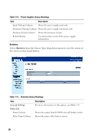
Page 26 highlights
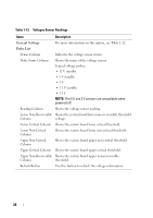
FILE LOCATION: D:\Projects\User Guide\Server\Dell\C6220II\BMC\C6220II_BMC_HOM_section1.fm Table 1-13. Voltages Sensor Readings Items Description General Settings For more information on this option, see Table 1-12. Probe List Status Column Indicates the voltage sensor status. Probe Name Column Shows the name of the voltage sensor. Typical voltage probes: • 12 V standby • 5 V standby • 5V • 3.3 V standby • 3.3 V NOTE: The 5 V and 3 V sensors are unavailable when powered off. Reading Column Shows the voltage sensor reading. Lower Non-Recoverable Shows the system board lower non-recoverable threshold Column voltage. Lower Critical Column Shows the system board lower critical threshold. Lower Non-Critical Column Shows the system board lower non-critical threshold. Upper Non-Critical Column Shows the system board upper non-critical threshold. Upper Critical Column Shows the system board upper critical threshold. Upper Non-Recoverable Shows the system board upper non-recoverable Column threshold. Refresh Button Use this button to refresh the voltage information. 26
-
 1
1 -
2
-
3
-
4
-
5
-
6
-
7
-
8
-
9
-
10
-
11
-
12
-
13
-
14
-
15
-
16
-
17
-
18
-
19
-
20
-
 21
21 -
 22
22 -
 23
23 -
 24
24 -
 25
25 -
 26
26 -
 27
27 -
 28
28 -
 29
29 -
 30
30 -
 31
31 -
32
-
33
-
34
-
35
-
36
-
37
-
38
-
39
-
40
-
41
-
42
-
43
-
44
-
45
-
46
-
47
-
48
-
49
-
50
-
51
-
52
-
53
-
54
-
55
-
56
-
57
-
58
-
59
-
60
-
61
-
62
 |
 |
