Dell PowerEdge M420 Dell PowerEdge M520 Systems Owner's Manual - Page 8
Hard-Drive Indicator Patterns, Drive-Status Indicator Pattern
 |
View all Dell PowerEdge M420 manuals
Add to My Manuals
Save this manual to your list of manuals |
Page 8 highlights
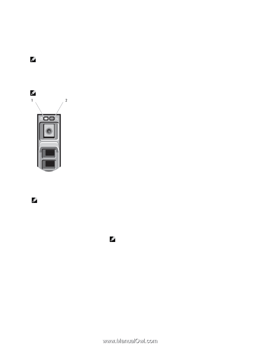
Hard-Drive Indicator Patterns Your system supports two 2.5 inch SSD, SAS or SATA hard drives. NOTE: SSD/SAS/SATA hard drives cannot be mixed within a blade. The hard-disk drives plug into the hard-drive backplane inside the blade. On blades with a diskless configuration, all hard drive slots must be filled with hard-drive blanks, and the hard-drive backplane must still be installed to maintain proper airflow. The hard-drive indicators display different patterns as drive events occur in the system. NOTE: The blade must have a hard drive or a hard-drive blank installed in each hard-drive bay. Figure 2. Hard-Drive Indicators 1. hard-drive activity indicator (green) 2. hard-drive status indicator (green and amber) NOTE: If the hard drive is in Advanced Host Controller Interface (AHCI) mode, the status LED (on the right side) does not function and remains off. Drive-Status Indicator Pattern Blinks green two times per second Off Blinks green, amber, and off Blinks amber four times per second Blinks green slowly Steady green Condition Identifying drive or preparing for removal Drive ready for insertion or removal NOTE: The drive status indicator remains off until all hard drives are initialized after system power is applied. Drives are not ready for insertion or removal during this time. Drive predicted failure Drive failed Drive rebuilding Drive online 8
-
 1
1 -
2
-
 3
3 -
 4
4 -
 5
5 -
 6
6 -
 7
7 -
 8
8 -
 9
9 -
 10
10 -
 11
11 -
 12
12 -
 13
13 -
14
-
15
-
16
-
17
-
18
-
19
-
20
-
21
-
22
-
23
-
24
-
25
-
26
-
27
-
28
-
29
-
30
-
31
-
32
-
33
-
34
-
35
-
36
-
37
-
38
-
39
-
40
-
41
-
42
-
43
-
44
-
45
-
46
-
47
-
48
-
49
-
50
-
51
-
52
-
53
-
54
-
55
-
56
-
57
-
58
-
59
-
60
-
61
-
62
-
63
-
64
-
65
-
66
-
67
-
68
-
69
-
70
-
71
-
72
-
73
-
74
-
75
-
76
-
77
-
78
-
79
-
80
-
81
-
82
-
83
-
84
-
85
-
86
-
87
-
88
-
89
-
90
-
91
-
92
-
93
-
94
-
95
-
96
-
97
-
98
-
99
-
100
-
101
-
102
-
103
-
104
-
105
-
106
-
107
-
108
-
109
-
110
-
111
-
112
-
113
-
114
-
115
-
116
-
117
-
118
-
119
-
120
-
121
-
122
-
123
-
124
-
125
-
126
-
127
-
128
-
129
 |
 |