Dell PowerEdge R420 Owner's Manual - Page 11
Front-Panel Features and Indicators-Four 3.5 Inch Cabled Hard-Drive System, Video connector - bios
 |
View all Dell PowerEdge R420 manuals
Add to My Manuals
Save this manual to your list of manuals |
Page 11 highlights
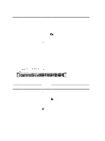
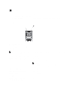
Item Indicator, Button, or Icon Description Connector 3 System identification button The identification buttons on the front and back panels can be used to locate a particular system within a rack. When one of these buttons is pressed, the LCD panel on the front and the system status indicator on the back flashes until one of the buttons is pressed again. Press to toggle the system ID on and off. If the system stops responding during POST, press and hold the system ID button for more than five seconds to enter BIOS progress mode. To reset iDRAC (if not disabled in F2 iDRAC setup) press and hold the button for more than 15 seconds. 4 USB connectors (2) Allows you to connect USB devices to the system. The ports are USB 2.0-compliant. 5 Optical drive (optional) One optional ultra slim SATA DVD-ROM drive or DVD+/RW drive. 6 LCD menu buttons Allows you to navigate the control panel LCD menu. 7 LCD panel Displays system ID, status information, and system error messages. The LCD lights blue during normal system operation. The LCD lights amber when the system needs attention, and the LCD panel displays an error code followed by descriptive text. NOTE: If the system is connected to a power source and an error is detected, the LCD lights amber regardless of whether the system is turned on or off. 8 Information tag 9 Video connector A slide-out label panel which allows you to record system information such as Service Tag, NIC, MAC address, and so on as per your need. Allows you to connect a VGA display to the system. 10 Hard drives Up to eight 2.5 inch hard drives, or SSDs. Figure 3. Front-Panel Features and Indicators-Four 3.5 Inch Cabled Hard-Drive System 11
-
 1
1 -
2
-
3
-
4
-
5
-
 6
6 -
 7
7 -
 8
8 -
 9
9 -
 10
10 -
 11
11 -
 12
12 -
 13
13 -
 14
14 -
 15
15 -
 16
16 -
17
-
18
-
19
-
20
-
21
-
22
-
23
-
24
-
25
-
26
-
27
-
28
-
29
-
30
-
31
-
32
-
33
-
34
-
35
-
36
-
37
-
38
-
39
-
40
-
41
-
42
-
43
-
44
-
45
-
46
-
47
-
48
-
49
-
50
-
51
-
52
-
53
-
54
-
55
-
56
-
57
-
58
-
59
-
60
-
61
-
62
-
63
-
64
-
65
-
66
-
67
-
68
-
69
-
70
-
71
-
72
-
73
-
74
-
75
-
76
-
77
-
78
-
79
-
80
-
81
-
82
-
83
-
84
-
85
-
86
-
87
-
88
-
89
-
90
-
91
-
92
-
93
-
94
-
95
-
96
-
97
-
98
-
99
-
100
-
101
-
102
-
103
-
104
-
105
-
106
-
107
-
108
-
109
-
110
-
111
-
112
-
113
-
114
-
115
-
116
-
117
-
118
-
119
-
120
-
121
-
122
-
123
-
124
-
125
-
126
-
127
-
128
-
129
-
130
-
131
-
132
-
133
-
134
-
135
-
136
-
137
 |
 |