Dell PowerEdge R420 Owner's Manual - Page 99
Installing The System Board, Removing and Installing the System Board
 |
View all Dell PowerEdge R420 manuals
Add to My Manuals
Save this manual to your list of manuals |
Page 99 highlights
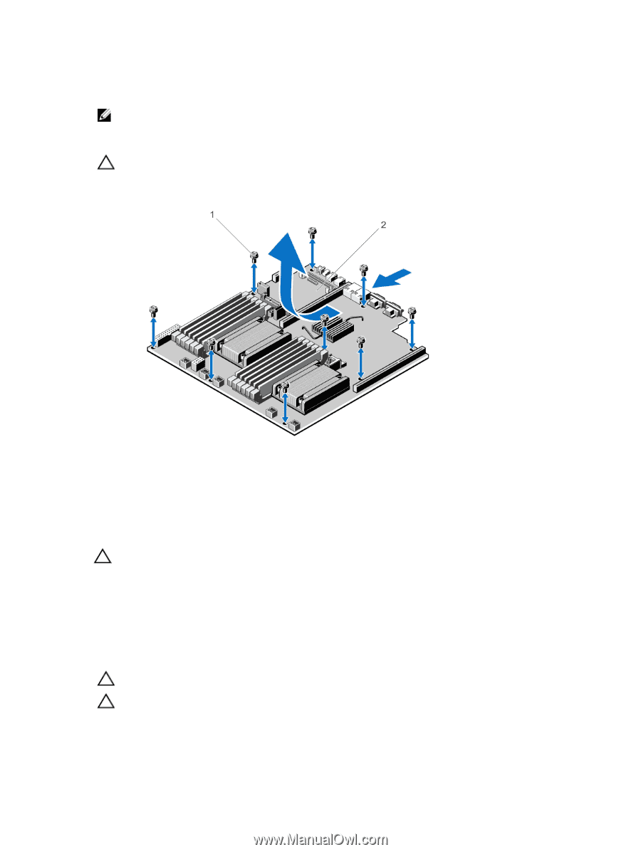
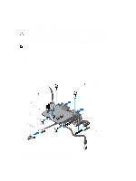
h) internal dual SD module i) expansion card holder NOTE: It is recommended that you remove the power distribution board before removing the system board from the chassis. 5. Disconnect all other cables from the system board. CAUTION: Do not lift the system board assembly by grasping a memory module, processor, or other components. 6. Remove the nine screws on the system board and slide the system board toward the front of the system. 7. Slide the system board toward the front of the system. Figure 58. Removing and Installing the System Board 1. screws (9) 2. system board Installing The System Board CAUTION: Many repairs may only be done by a certified service technician. You should only perform troubleshooting and simple repairs as authorized in your product documentation, or as directed by the online or telephone service and support team. Damage due to servicing that is not authorized by Dell is not covered by your warranty. Read and follow the safety instructions that came with the product. 1. Unpack the new system board assembly. 2. Transfer the following components to the new system board: a) heat sink(s)/heat-sink blank(s) and processors(s)/processor blank(s) b) memory modules and memory module blanks CAUTION: Do not lift the system board assembly by grasping a memory module, processor, or other components. CAUTION: Take care not to damage the system identification button while placing the system board into the chassis. 3. Hold and align the system board by its edges and align it to the back of the chassis. 99
-
 1
1 -
2
-
3
-
4
-
5
-
6
-
7
-
8
-
9
-
10
-
11
-
12
-
13
-
14
-
15
-
16
-
17
-
18
-
19
-
20
-
21
-
22
-
23
-
24
-
25
-
26
-
27
-
28
-
29
-
30
-
31
-
32
-
33
-
34
-
35
-
36
-
37
-
38
-
39
-
40
-
41
-
42
-
43
-
44
-
45
-
46
-
47
-
48
-
49
-
50
-
51
-
52
-
53
-
54
-
55
-
56
-
57
-
58
-
59
-
60
-
61
-
62
-
63
-
64
-
65
-
66
-
67
-
68
-
69
-
70
-
71
-
72
-
73
-
74
-
75
-
76
-
77
-
78
-
79
-
80
-
81
-
82
-
83
-
84
-
85
-
86
-
87
-
88
-
89
-
90
-
91
-
92
-
93
-
 94
94 -
 95
95 -
 96
96 -
 97
97 -
 98
98 -
 99
99 -
 100
100 -
 101
101 -
 102
102 -
 103
103 -
 104
104 -
105
-
106
-
107
-
108
-
109
-
110
-
111
-
112
-
113
-
114
-
115
-
116
-
117
-
118
-
119
-
120
-
121
-
122
-
123
-
124
-
125
-
126
-
127
-
128
-
129
-
130
-
131
-
132
-
133
-
134
-
135
-
136
-
137
 |
 |