Dell PowerEdge R420 Owner's Manual - Page 41
Installing The Cooling Shroud, System Memory
 |
View all Dell PowerEdge R420 manuals
Add to My Manuals
Save this manual to your list of manuals |
Page 41 highlights
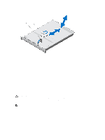
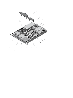
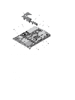
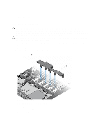
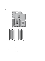
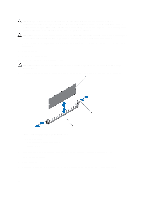
Installing The Cooling Shroud CAUTION: Many repairs may only be done by a certified service technician. You should only perform troubleshooting and simple repairs as authorized in your product documentation, or as directed by the online or telephone service and support team. Damage due to servicing that is not authorized by Dell is not covered by your warranty. Read and follow the safety instructions that came with the product. NOTE: For proper seating of the cooling shroud in the chassis, ensure that the cables inside the system are routed through the cable routing latch. 1. Align the cooling shroud with the numbered fan bays as a guide. 2. Lower the cooling shroud into the chassis. When firmly seated, the memory socket numbers marked on the cooling shroud align with the respective memory sockets and the four tabs on the cooling shroud rest on the cooling fan bracket. 3. Close the system. 4. Reconnect the system to its electrical outlet and turn the system on, including any attached peripherals. System Memory Your system supports DDR3 unbuffered ECC DIMMs (UDIMM ECC) and registered DIMMs (RDIMMs). It supports DDR3 and DDR3L voltage specifications. NOTE: MT/s indicates DIMM speed in MegaTransfers per second. Memory bus operating frequency can be 1600 MT/s, 1333 MT/s, 1066 MT/s, or 800 MT/s depending on: • DIMM type (UDIMM or RDIMM) • DIMM configuration (number of ranks) • maximum frequency of the DIMMs • number of DIMMs populated per channel • DIMM operating voltage • system profile selected (for example, Performance Optimized, Custom, or Dense Configuration Optimized) • maximum supported DIMM frequency of the processors The following table shows the memory populations and operating frequencies for the supported configurations. DIMM Type DIMMs Populated/ Channel UDIMM ECC 1 2 RDIMM 1 2 Operating Frequency (in MT/s) 1.5 V 1.35 V 1333, 1066, and 800 1333, 1066 and 800 1333, 1066, and 800 1066 and 800 1600, 1333, 1066 and 800 1333, 1066 and 800 1333, 1066 and 800 1066 and 800 1600, 1333, 1066, and 800 1333, 1066, and 800 1066 and 800 1066 and 800 Maximum DIMM Rank/ Channel Dual rank Dual rank Dual rank Quad rank Dual rank Quad rank 41
-
 1
1 -
2
-
3
-
4
-
5
-
6
-
7
-
8
-
9
-
10
-
11
-
12
-
13
-
14
-
15
-
16
-
17
-
18
-
19
-
20
-
21
-
22
-
23
-
24
-
25
-
26
-
27
-
28
-
29
-
30
-
31
-
32
-
33
-
34
-
35
-
 36
36 -
 37
37 -
 38
38 -
 39
39 -
 40
40 -
 41
41 -
 42
42 -
 43
43 -
 44
44 -
 45
45 -
 46
46 -
47
-
48
-
49
-
50
-
51
-
52
-
53
-
54
-
55
-
56
-
57
-
58
-
59
-
60
-
61
-
62
-
63
-
64
-
65
-
66
-
67
-
68
-
69
-
70
-
71
-
72
-
73
-
74
-
75
-
76
-
77
-
78
-
79
-
80
-
81
-
82
-
83
-
84
-
85
-
86
-
87
-
88
-
89
-
90
-
91
-
92
-
93
-
94
-
95
-
96
-
97
-
98
-
99
-
100
-
101
-
102
-
103
-
104
-
105
-
106
-
107
-
108
-
109
-
110
-
111
-
112
-
113
-
114
-
115
-
116
-
117
-
118
-
119
-
120
-
121
-
122
-
123
-
124
-
125
-
126
-
127
-
128
-
129
-
130
-
131
-
132
-
133
-
134
-
135
-
136
-
137
 |
 |