Dell PowerEdge R420 Owner's Manual - Page 85
Cabling Diagram-Four Hard-Drive Backplane
 |
View all Dell PowerEdge R420 manuals
Add to My Manuals
Save this manual to your list of manuals |
Page 85 highlights
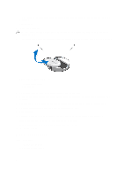
Figure 45. Cabling Diagram-Four Hard-Drive Backplane 1. system board 2. hard-drive backplane 3. SAS cable connector 4. cable routing guide 5. signal cable connector 6. power cable connector 7. cable routing latch 8. power distribution board 9. cable retention latch Figure 46. Front View of the Eight Hard-Drive Backplane 1. hard-drive connectors (8) 85
-
 1
1 -
2
-
3
-
4
-
5
-
6
-
7
-
8
-
9
-
10
-
11
-
12
-
13
-
14
-
15
-
16
-
17
-
18
-
19
-
20
-
21
-
22
-
23
-
24
-
25
-
26
-
27
-
28
-
29
-
30
-
31
-
32
-
33
-
34
-
35
-
36
-
37
-
38
-
39
-
40
-
41
-
42
-
43
-
44
-
45
-
46
-
47
-
48
-
49
-
50
-
51
-
52
-
53
-
54
-
55
-
56
-
57
-
58
-
59
-
60
-
61
-
62
-
63
-
64
-
65
-
66
-
67
-
68
-
69
-
70
-
71
-
72
-
73
-
74
-
75
-
76
-
77
-
78
-
79
-
 80
80 -
 81
81 -
 82
82 -
 83
83 -
 84
84 -
 85
85 -
 86
86 -
 87
87 -
 88
88 -
 89
89 -
 90
90 -
91
-
92
-
93
-
94
-
95
-
96
-
97
-
98
-
99
-
100
-
101
-
102
-
103
-
104
-
105
-
106
-
107
-
108
-
109
-
110
-
111
-
112
-
113
-
114
-
115
-
116
-
117
-
118
-
119
-
120
-
121
-
122
-
123
-
124
-
125
-
126
-
127
-
128
-
129
-
130
-
131
-
132
-
133
-
134
-
135
-
136
-
137
 |
 |
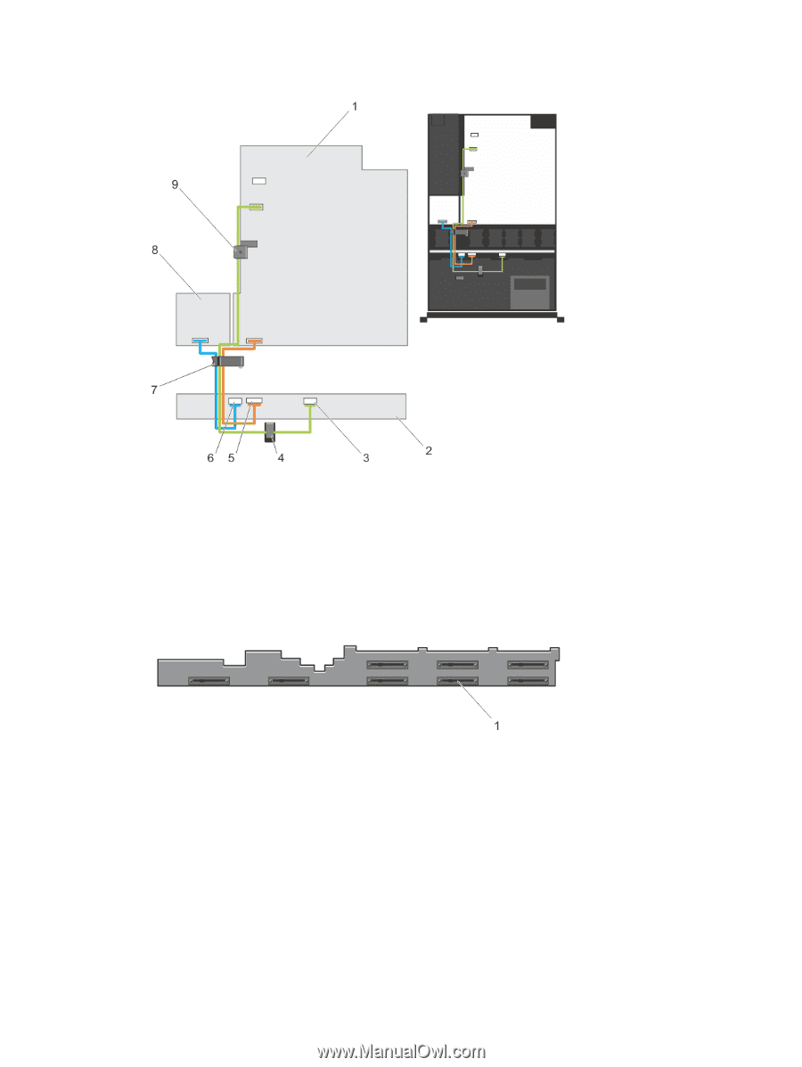
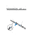
Figure 45. Cabling Diagram—Four Hard-Drive Backplane
1. system board
2. hard-drive backplane
3. SAS cable connector
4. cable routing guide
5. signal cable connector
6. power cable connector
7. cable routing latch
8. power distribution board
9. cable retention latch
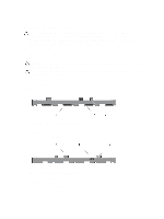
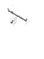
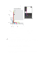
Figure 46. Front View of the Eight Hard-Drive Backplane
1. hard-drive connectors (8)
85